Circuit symbols and circuit diagrams
“
recall and use the circuit symbols shown in section 6 of this syllabus; draw and interpret circuit diagrams containing the circuit symbols shown in section 6 of this syllabus
A shared language
Every circuit question is drawn with standard symbols, and each symbol has one exact meaning: a plain rectangle is a resistor, a rectangle with a bent line through it is a thermistor, a circle with a V inside is a voltmeter. Paper 2 often asks you to draw a circuit from a written description (2–3 marks), and Paper 1 often asks you to identify a component from its symbol. Both need the same vocabulary, so learn the two sheets below by shape.
The symbols used in almost every circuit in this topic. The long, thin plate of a cell is its positive terminal.
The rest of the syllabus list: supplies, heating and semiconductor parts, and the output and input devices. Multiple-choice questions ask you to pick out the buzzer, the microphone or the oscilloscope from symbols like these.
The two meter rules
Meters are components with a job, and their position is part of the answer:
- An ammeter counts the charge flowing through a branch, so it is connected in series in that branch — the same current then passes through the meter and the component.
- A voltmeter compares energy per coulomb between two points, so it is connected in parallel across the component whose p.d. it reads.
Both rules are marked directly. In "draw a circuit to measure resistance", one mark is for a closed loop with correct symbols and one is for the ammeter in series and the voltmeter in parallel with the component. The galvanometer is a third meter: a sensitive current detector used to find the point where the current is zero. You use it in the "Potentiometers and null methods" section.
Components one after another in a single path, with no junction between them, are in series: the same current passes through each. Components connected between the same two junctions (dots where three or more wires meet) are in parallel: the current splits between them. A voltmeter's branch is not part of the main loop, because (almost) no current flows through a voltmeter.
What the examiner checks in a drawing
When a Paper 2 question says draw, four things decide the marks:
- Closed loop. The circuit is one unbroken loop through the source, with no gaps.
- Correct symbols, drawn clearly. A symbol that could be read as something else does not earn the symbol mark.
- Nothing extra. One mark scheme reads "all correct symbols in series and no extra symbols": a component the question never mentioned loses that mark.
- Meters in the right place. The ammeter in the branch it measures; the voltmeter across exactly the component named. A voltmeter across the battery, or across two components instead of one, loses the mark.
From words to wires
A cell drives a current through a fixed resistor and a thermistor connected in series. An ammeter reads the circuit current and a voltmeter reads the p.d. across the fixed resistor. Draw the circuit diagram.
Show full working
The finished diagram: one series loop, with the voltmeter bridging the fixed resistor only.
- 1
Draw the source first: a cell (long, thin plate = positive terminal).
start with the source; the loop is built round it
- 2
The description says series: cell, ammeter, fixed resistor and thermistor form ONE closed loop — draw them in order and join the ends.
series means a single loop carrying one current everywhere
- 3
Put the ammeter in the loop itself, so the circuit current passes through it.
an ammeter counts the charge in its own branch — it must be in series
- 4
Add the voltmeter as a branch, not a loop element: a parallel connection across the fixed resistor only.
a voltmeter compares two points — it must bridge exactly the component named
A single loop — cell, ammeter, fixed resistor, thermistor — with the voltmeter connected in parallel across the fixed resistor alone.
The voltmeter's position earns its own mark. A voltmeter across the cell, or across the resistor and thermistor together, loses that mark even when every symbol is perfect.
Your turn
Try each one on paper before opening the solution, especially the drawings.
- 19702/24 O/N 2025 Q5(a)(ii)2 marks
A student uses a circuit containing an ammeter, a voltmeter and a cell to take measurements to determine the resistance of a length of nichrome wire. Draw a circuit diagram to show how the components should be connected. Use the symbol for a resistor to represent the nichrome wire.
Stuck? Show hint
One mark is about the loop and the symbols; the other is about where each meter sits.
Show solution
- 1
Draw one closed loop — cell, ammeter, nichrome wire (as a resistor symbol) — using correct standard symbols throughout.
MS B1: resistor connected to cell in a closed loop, correct symbols for all components
- 2
Connect the voltmeter in parallel across the resistor symbol only.
MS B1: ammeter in series with the resistor, voltmeter in parallel with it
AnswerA single series loop of cell, ammeter and resistor (the nichrome wire), with the voltmeter in parallel across the resistor alone.
- 1
- 29702/23 M/J 2023 Q5(a)3 marks
A student sets up a circuit with a battery, an ammeter, a heater and a light-dependent resistor (LDR) all in series. The battery has negligible internal resistance. A voltmeter is connected across (in parallel with) the heater.
On Fig. 5.1, complete the circuit diagram of this arrangement.
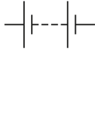
Fig. 5.1
Stuck? Show hint
Three marks: one symbol, the whole series loop, and the voltmeter's branch.
Show solution
- 1
Draw the heater with its standard symbol (a rectangle divided into four compartments) and the LDR (a resistor rectangle with two arrows pointing in, to show light falling on it).
MS M1: correct symbol for the heater or for the LDR
- 2
Connect battery, ammeter, heater and LDR in one series loop, adding no other components.
MS A1: all correct symbols in series (voltmeter ignored) and no extra symbols
- 3
Add the voltmeter in parallel across the heater only.
MS B1: correct voltmeter symbol, in parallel with the heater
AnswerBattery, ammeter, heater (four-compartment rectangle) and LDR in a single series loop, with a voltmeter in parallel across the heater.
- 1
- 39702/12 F/M 2025 Q341 mark
Which circuit symbol does not represent an electric component that is designed to emit sound waves?

Options A–D
Stuck? Show hint
Three of the four are the bell, the buzzer and the loudspeaker. What is the fourth?
Show solution
- 1
A is a half-circle with the wires joined to its flat side: an electric bell. D is a half-circle with the wires joined to its curved side: a buzzer. C is a small box with a flared cone: a loudspeaker. All three are designed to emit sound.
eliminate the sound emitters first. Bell and buzzer differ only in which side the wires join
- 2
B is a rectangle divided into four compartments: the symbol for a heater. A heater is designed to transfer thermal energy, not to emit sound.
the odd one out belongs to a different family
AnswerB — the four-compartment rectangle is a heater. The electric bell (A), loudspeaker (C) and buzzer (D) all emit sound.
- 1
The rest of this note
Can you do all of these?
Draw the common symbols from memory (cell, battery, resistor, variable resistor, thermistor, LDR, lamp, heater, switch, ammeter, voltmeter, galvanometer, potentiometer) and recognise the rest (power supplies, diode, LED, fuse, bell, buzzer, loudspeaker, microphone, motor, generator, oscilloscope, earth)
Place an ammeter IN SERIES with the component whose current it measures, and a voltmeter IN PARALLEL with the component whose p.d. it measures
Define e.m.f. word for word, and distinguish it from p.d.: at an e.m.f. energy is transferred to electrical form; across a p.d. electrical energy is transferred to other forms
Model a real source as an e.m.f. E in series with an internal resistance r; use V = E − Ir, where Ir is the lost volts
More current → more lost volts → lower terminal p.d. The e.m.f. does not change
Read E (intercept) and r (−gradient) from a graph of terminal p.d. against current, converting mA to A
State Kirchhoff's first law (sum of currents into a junction = sum out; conservation of charge)
State Kirchhoff's second law (sum of e.m.f.s = sum of p.d.s around a closed loop; conservation of energy)
Derive the series and parallel formulae from Kirchhoff's laws when asked to 'show that'
In a loop with more than one cell, count each e.m.f. + or − according to which way the cell faces
Reduce a network one step at a time, redrawing after each step, and convert every prefix (kΩ, mA) before substituting
Treat a closed switch or wire across a component as a short circuit: no current in the component, zero p.d. across it
Use V_out = V_in × R₂/(R₁ + R₂), recalculating the total whenever a resistance changes or a load is added
Find the potential of a point from a 0 V line; a meter between two points reads the difference; zero reading means equal ratios in the two dividers
Explain sensor circuits as a chain, one link per sentence, ending with a direction word
Potentiometer: balance when the galvanometer reads zero, so no current is taken from the cell; E_x/V_wire = L_balance/L_wire; the wire must be uniform; the cells must oppose