Period, frequency and peak value
“
understand and use the terms period, frequency and peak value as applied to an alternating current or voltage
A current that never sits still
Every current and voltage you met in AS Electricity was, sooner or later, treated as a fixed number: a battery drives 2.0 A through a resistor, a p.d. of 6.0 V sits across it, and that is the whole story until something in the circuit changes. Mains electricity is not like that. A generator — a coil rotating in a magnetic field, exactly the mechanism built in the Magnetic Fields note — produces a current that climbs from zero to a maximum, falls back through zero, climbs the other way to a maximum in the opposite direction, and repeats this cycle continuously, fifty or sixty times every second. There is no single number that is "the current" any more. The current is a function of time.
This is an alternating current (a.c.): a current (or voltage) whose direction reverses periodically, its magnitude tracing out the same repeating shape forever. Describing it needs three new ideas that a steady d.c. supply never needed at all.
The three descriptors
- Period, — the time taken for the current or voltage to complete exactly one full cycle: from some starting value, through every value the wave takes, back to that same value with the same direction of change. Measured in seconds.
- Frequency, — the number of complete cycles occurring every second. Measured in hertz (Hz), where cycle per second. Period and frequency are reciprocals of each other: a wave that repeats every completes cycles every second.
- Peak value, — the maximum magnitude the alternating quantity reaches in either direction during a cycle. For a voltage this is written , for a current . It is not some kind of average over the cycle — the average of a symmetric alternating quantity over a full cycle is zero, since positive and negative halves cancel. The peak is the single largest instantaneous departure from zero, on either side.
A d.c. supply never needed any of these three, because a constant quantity has no period to measure, no frequency to count, and its "peak" is just itself. They exist specifically because the a.c. quantity keeps changing.
Period and frequency are reciprocals: T in seconds, f in hertz (cycles per second).
Where comes from
Sketch one cycle of an alternating current and it looks exactly like the graph you have already drawn for simple harmonic motion in the Oscillations note, or for a point going round a circle in Motion in a Circle: a smooth, repeating wave. That is not a coincidence — a sinusoidally alternating current is mathematically identical to the projection of steady circular motion onto one axis, and it inherits the same angular frequency , measured in radians per second.
In circular motion, a full revolution sweeps through radians, and takes one period to do it, so the rate of sweeping — the angular frequency — is
Since , this can equally be written the other way, in terms of frequency:
Both forms say the same thing: is (one full cycle, in radians) shared out over however long — or however often — that cycle happens. It is the single number that appears inside the sine or cosine in every equation this note uses, and §02 puts it to work.
Angular frequency — the same ω as circular motion and SHM. Rearranges to T = 2π/ω or f = ω/2π.
rad s⁻¹
- 1
Read the peak value straight off: it is the number multiplying the sin (or cos), with no further work needed.
The coefficient in front is defined to be the maximum the function ever reaches, since sin and cos themselves never exceed 1 in size.
- 2
Read the angular frequency straight off: it is the number multiplying inside the sin (or cos) — not the frequency, and not the period.
This is the step most often rushed. Whatever sits next to t inside the bracket is ω in rad s⁻¹, full stop — it has to be converted before it becomes T or f.
- 3
Convert to the period: .
Rearranging ω = 2π/T for T. Keep the answer in seconds unless a question specifically asks for ms or µs.
- 4
Convert to the frequency, if asked: , or equivalently using the value just found.
Both routes must agree — computing f both ways is a free check that nothing was mixed up along the way.
Invented demo — reading everything off one equation
An alternating voltage is given by , where is in volts and is in seconds.
State (i) the peak voltage, (ii) the angular frequency, (iii) the period, (iv) the frequency.
Show full working
- 1
(i) Peak value: the coefficient in front of the sine is , so
No calculation — just reading the number that sin(...) is multiplied by.
- 2
(ii) Angular frequency: the coefficient multiplying inside the bracket is , so
Again, read directly — this is exactly the number sitting next to t, nothing more.
- 3
(iii) Period: apply with the value just found:
The π's cancel exactly, which is exactly why these problems are built around multiples of π — it is a built-in check that the substitution went in correctly.
- 4
(iv) Frequency: apply :
Cross-check using — the two routes agree.
Computing f a second way, from T, is free insurance: if the two answers disagreed, a mistake happened somewhere upstream.
V0 = 12 V; ω = 100π rad s⁻¹; T = 0.020 s (20 ms); f = 50 Hz.
This exact voltage is plotted in the figure below — check that the marked period and peak match the numbers just found before moving on.
V = 12 sin(100πt), plotted from t = 0 to 40 ms — two complete cycles. The curve starts at zero and rises (the sin signature), reaches +12 V a quarter-period later, and completes one full cycle every T = 20 ms, matching the values found in the worked example above.
A real 'show that' — period from angular frequency
An alternating voltage varies with time according to , where is in volts and is in seconds.
Show that the period of the voltage is .
Show full working
- 1
Read off : the coefficient multiplying is , so
The rule from the method box applies identically to cos as to sin — the period only depends on ω, not on which trig function carries it.
- 2
Apply :
The π's cancel again. A 'show that' question wants this substitution written out, not just the final number copied from a calculator.
T = 2π/ω = 2π/40π = 0.050 s, as required.
For a 'show that' mark, always display the substitution with the given numbers plugged in — the examiner is checking the method, and the printed answer is there to check your arithmetic, not to be quoted without working.
Period from an angular frequency established earlier in the question
The circuit in Fig. 6.1 is supplied with an alternating input voltage. An earlier part of the question establishes that this supply has angular frequency .
Show that the period of the input voltage is .
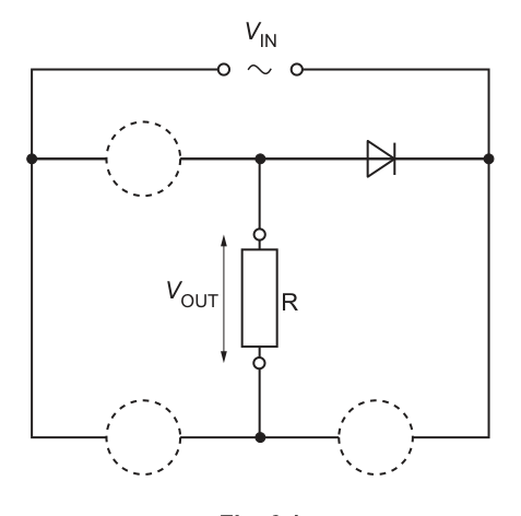
Fig. 6.1 from the question paper: part of a bridge rectifier circuit, with four diodes (one already drawn) and the output voltage V_OUT taken across a load resistor R. Later parts of this same question (§06–§07) complete the rectifier and analyse V_OUT — here only the period of the alternating input is needed.
Show full working
- 1
Name the relation:
Same rearrangement of ω = 2π/T as every question in this section — the relation does not care what the circuit around it looks like.
- 2
Substitute :
This time there is no neat π cancellation — 18 is not a multiple of π, so the answer must be evaluated as a decimal instead.
- 3
Evaluate to more figures than needed, then round to check against the given answer:
Carrying an extra figure before rounding is what makes a 'show that' answer trustworthy — rounding too early can land on the wrong final digit even when the method is correct.
T = 2π/18 = 0.35 s (2 s.f.).
Whenever a 'show that' target has no obvious exact simplification (no clean π cancellation), that is the signal to evaluate a decimal answer to 3+ significant figures before rounding to compare.
Determining the constants in V = A cos(Bt) from a graph
Fig. 6.2 shows the variation with time of the alternating input voltage to a rectifying circuit: its peak value is and its period is . The variation of with can be represented by
Determine , stating an appropriate unit, and determine .
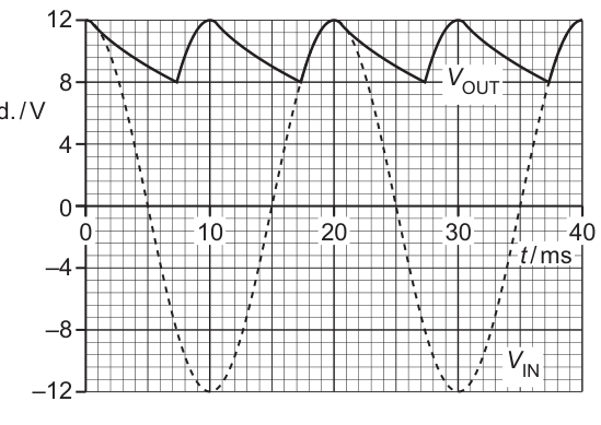
Fig. 6.2 from the question paper: the variations with time t of the input p.d. V_IN and the rectified output p.d. V_OUT. V_IN is the sinusoid running between −12 V and +12 V, repeating every 20 ms.
Show full working
- 1
Identify by matching to the general form: comparing with shows that plays the role of the peak value, which Fig. 6.2 gives directly:
A is exactly the x0 of the method box — the coefficient in front of the cosine — so it is read straight off the graph's peak with no calculation.
- 2
Identify by the same matching: plays the role of , so it must be found from the given period using .
Naming which symbol plays which role BEFORE substituting avoids the common mix-up of quoting the period itself as if it were B.
- 3
Convert the period to seconds: .
The conversion is written out as its own step, before it goes anywhere near a formula — exactly the habit that protects a ×1000 error in the next line.
- 4
Substitute and evaluate:
2π ÷ 0.020 — carried to more figures before rounding, matching the scheme's own 2 s.f. answer of 310 rad s⁻¹.
A = 12 V; B = 2π/(20×10⁻³) = 310 rad s⁻¹ (2 s.f.).
Whenever a question writes an alternating quantity with unfamiliar letters (A, B, X, Y — anything but x0 and ω), the first move is always the same: match each letter to its role in x = x0 sin(ωt) or x0 cos(ωt) before substituting anything.
Reading the number next to as the frequency , e.g. taking and writing "".
The number next to inside sin/cos is always the angular frequency , in rad s⁻¹. Convert with .
ω and f differ by a factor of 2π — treating them as interchangeable is the single most common slip in this section, and it silently corrupts every period or frequency calculated afterwards.
Substituting a period given in ms or µs directly into without converting to seconds.
Convert to seconds first: , written as its own step before substituting.
ω comes out 1000× (or 10⁶×) too large otherwise — a mistake that produces a plausible-looking wrong number, which is exactly why examiners tag the conversion separately.
Treating the peak value as some kind of "typical" or average size of the alternating quantity.
is the single largest instantaneous value reached; the true cycle average of a symmetric a.c. quantity is zero.
This distinction matters even more once §03 introduces the r.m.s. value — a genuinely different 'effective size' that is neither the peak nor the (zero) average.
Your turn
One reading-off drill adapted from a real graph question, then two invented conversions between f, T and ω.
- 13 marks
An alternating current is given by . A graph of the current against time shows a peak value of and a period of .
Find and , giving an appropriate unit for each.Stuck? Show hint
is read straight off the graph's peak height; comes from the period using .
Show solution
- 1
Peak value: read directly from the graph,
No calculation needed — the peak height on a graph IS the peak value, by definition.
- 2
Angular frequency: apply with :
Carrying extra figures before rounding — 157 rounds UP to 160 at 2 s.f., which is easy to get wrong by rounding 157 down instead.
AnswerI0 = 0.85 A; ω = 2π/0.040 = 160 rad s⁻¹ (2 s.f.).
- 1
- 23 marks
The alternating mains supply in a certain country has frequency .
Calculate (i) the period, (ii) the angular frequency of the supply.Stuck? Show hint
Period is the direct reciprocal of frequency; angular frequency follows from either T or f.
Show solution
- 1
(i) Apply :
The defining reciprocal relationship — no intermediate steps needed, just the substitution.
- 2
(ii) Apply directly from the given frequency:
Using f directly (rather than going via T first) is faster and avoids compounding any rounding from part (i).
Answer(i) T = 1/60 = 16.7 ms. (ii) ω = 2π×60 = 377 rad s⁻¹.
- 1
- 33 marks
An alternating voltage has period .
Calculate (i) the frequency, (ii) the angular frequency.Stuck? Show hint
Convert the period to seconds before either calculation.
Show solution
- 1
Convert the period: .
Written out before either formula is touched — the habit that prevents a ×1000 slip.
- 2
(i) Apply :
A clean round number here is a good sign the conversion in the previous step was correct.
- 3
(ii) Apply :
Using the frequency just found, rather than recomputing 2π/T from scratch, re-uses the working already checked in part (i).
AnswerT = 4.0×10⁻³ s; (i) f = 250 Hz. (ii) ω = 2π×250 = 1570 rad s⁻¹.
- 1
The rest of this note
Can you do all of these?
Recognise that an alternating quantity needs three new descriptors a steady one never did: period T, frequency f = 1/T, and peak value x0
Get ω from the equation, not from guessing — it is always the coefficient multiplying t inside the sin/cos, in rad s⁻¹
Convert ω to T with T = 2π/ω, and to f with f = ω/2π = 1/T — never confuse ω (rad s⁻¹) with f (Hz)
Convert any time given in ms or µs to seconds before substituting into ω = 2π/T
Read the peak value x0 straight off the coefficient in front of sin/cos — it is not the r.m.s. value (§03) and not the mean
Before sketching, check whether the function is sin (starts at zero, rising) or cos (starts at the peak) — the two are mirror images shifted by a quarter period
When reading a sketch back into an equation, get T from the distance between two consecutive peaks (or two consecutive zero up-crossings), and read x0 straight off the peak height
Square a sinusoid and its mean over a cycle is ½ of the peak — derive it (sin²θ = (1−cos2θ)/2, or the graph symmetry argument), don't just quote it
Get rms FROM mean power (Irms²R = I0²R/2 ⇒ Irms = I0/√2), not as a separate rule to memorise — the √2 is a genuine square root, not a plain half
For a HALF-WAVE rectified sinusoid, mean power is a QUARTER of the peak, not a half — one factor of ½ from squaring-and-averaging, a second independent factor of ½ from the diode blocking half the cycle
Once values are r.m.s., P = IV = I²R = V²/R apply completely unchanged — no extra √2 or ½ anywhere
[legacy] Derive the transformer turns ratio from EQUAL flux linkage per turn in both coils, not by quoting it — and remember the current ratio is inverted relative to voltage/turns
[legacy] The core LINKS flux between the coils; lamination separately REDUCES eddy-current losses within the core itself — two different jobs, don't conflate them
[legacy] Name transformer losses specifically — winding resistance heating, hysteresis, eddy currents, flux leakage — 'it's not perfect' alone earns nothing
[pre-2022/IGCSE] Cable loss ∝ 1/V² for a fixed transmitted power — always state BOTH links (higher V ⇒ lower I; lower I ⇒ much lower I²R loss), not just the conclusion
[pre-2022/IGCSE] A transformer needs a CHANGING flux, so only a.c. (never steady d.c.) can be stepped up or down — this is why transmission must be alternating
Half-wave rectification: ONE diode, output is zero for half the cycle every cycle. Full-wave (bridge): FOUR diodes, output never goes zero-for-a-whole-half-cycle — it's the SAME polarity reversed, not removed
Trace a bridge rectifier's current path for BOTH half-cycles separately — the diode PAIR that conducts swaps, but the current direction THROUGH THE LOAD stays the same both times, which is the entire point
A smoothing capacitor sits in PARALLEL with the load, charges to (near) the peak, then discharges through the load once the diodes stop conducting — it is never charged by, or discharging into, anything else
The smoothing discharge equation is the Capacitance note's UNCHANGED — just with t measured from the most recent rectifier peak and x0 = the peak voltage
Bigger C or bigger R (either one, or both — τ = RC treats them symmetrically) increases the time constant, so the SAME fixed gap between peaks causes a SMALLER voltage drop — state the full chain (bigger τ ⇒ slower decay ⇒ smaller drop ⇒ smaller ripple), not just 'bigger is smoother'