Physics 9702/23 — October/November 2025
Cambridge AS Level · AS Level Structured Questions · worked solutions for every part, with the mark scheme
Topics Physical Quantities and Units · Electricity · Kinematics · Work, Energy and Power · Forces, Density and Pressure · Dynamics · +5 more
Answer
Acceleration is the rate of change of velocity with time.
Rate of change of velocity with time.
Background Concept
Acceleration describes how quickly velocity changes. Since velocity is a vector, acceleration is also a vector.
Mathematically, for motion along a straight line,
and, instantaneously,
Understanding the Question
You are asked for the definition of acceleration, not a calculation. So you should write it in words (or equivalently as a rate equation).
Approach
Use the standard kinematics definition: acceleration is a time rate of change of velocity.
Step-by-Step Reasoning
- Identify that acceleration compares how velocity changes over time.
- State this clearly: “rate of change of velocity with time”.
Key Takeaways
- Acceleration links directly to velocity via a time rate of change.
- Because velocity is a vector, acceleration has direction too.
Common Mistakes
- Writing “rate of change of speed” (speed is scalar; the standard definition is velocity).
- Defining it as “change in distance per time” (that is speed/velocity, not acceleration).
Things to Be Careful About
- Use the word velocity (or make clear it is a vector quantity).
- For definitions, keep it concise and unambiguous.
A rocket is launched vertically from the surface of the Earth.
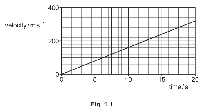
Fig. 1.1 shows the variation of the velocity of the rocket with time for the first after its launch.
Working
From the graph, the straight line passes through and .
Answer
16 m s^-2
Background Concept
For a velocity–time graph, the gradient gives the acceleration:
If the graph is a straight line, the acceleration is constant, so any two points on the line can be used.
Understanding the Question
The graph shows velocity increasing linearly from launch to . You are asked to determine the rocket’s acceleration, i.e. the gradient of the – graph.
From the given graph description, the line goes from to approximately .
Approach
- Pick two clear points on the straight line (best to use endpoints for accuracy).
- Compute the gradient using .
- Quote the value with unit .
Step-by-Step Reasoning
Take the endpoints:
- At , .
- At , .
Then
So
Key Takeaways
- Gradient of a – graph is acceleration.
- Straight-line – graph implies constant acceleration.
Common Mistakes
- Using instead of .
- Reading the velocity at incorrectly from the axis scale.
- Forgetting the unit .
Things to Be Careful About
- Use two widely separated points to reduce percentage reading error.
- Ensure you are using velocity (vertical axis) and time (horizontal axis) in the correct order for the gradient.
Show that the height of the rocket above the surface of the Earth at a time of after launch is .
Working
Height area under the – graph from to .
Triangle with base and height :
Answer
3.2 km
Background Concept
Displacement (and hence height for vertical motion) is found from velocity by integrating over time. On a velocity–time graph, this is represented by the area under the graph:
For straight-line segments, the area can be found using simple shapes (rectangles, triangles, trapezia).
Understanding the Question
You must show that at the rocket is above the launch point, using the velocity–time graph given (a straight line from at to at ).
Approach
- Recognise that height gained equals the area under the – graph from to .
- The line starts at the origin, so the region under the line is a triangle.
- Find its area and convert metres to kilometres.
Step-by-Step Reasoning
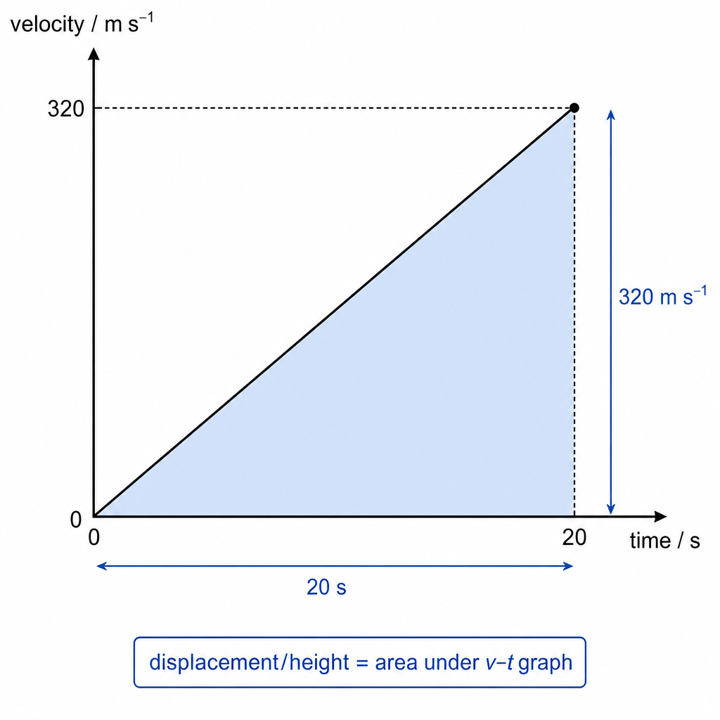
The graph is a straight line from to , so the area under it is a right triangle.
Base (time) .
Height (velocity) .
Area:
Convert to kilometres:
So the height at is .
Key Takeaways
- Area under a velocity–time graph gives displacement.
- With a straight-line increase from zero, displacement is the area of a triangle.
Common Mistakes
- Using the gradient (acceleration) instead of the area to find height.
- Calculating without the (that would be the area of the bounding rectangle, not the triangle).
- Forgetting to convert to .
Things to Be Careful About
- Keep track of units: .
- The question asks for height above the surface, so take displacement from to (not from some other time interval).
The mass of the rocket in (b) is . Assume that this mass remains constant.
For this rocket, from launch to its height at a time of after launch:
Working
Height gained in : .
Answer
9.1 × 10^10 J
Background Concept
A gain in gravitational potential energy near Earth’s surface is given by
where:
- is mass,
- is gravitational field strength (about near Earth’s surface),
- is vertical height gained.
Understanding the Question
The rocket has mass (assumed constant). From launch to it rises by (found in part (b)(ii)). You must calculate the increase in gravitational potential energy over this rise.
Approach
- Convert to metres.
- Substitute into .
- Give the answer in joules and standard form.
Step-by-Step Reasoning
Convert height:
Now substitute:
Multiply the powers of ten: , and multiply the numerical factors:
So
Key Takeaways
- Use for vertical motion near Earth.
- Always convert km to m before substitution.
Common Mistakes
- Using instead of (forgetting km to m conversion).
- Omitting or using incorrect units.
- Not giving the answer in joules or not using standard form for a large number.
Things to Be Careful About
- The question says mass remains constant, so you do not need to account for fuel burn.
- Using instead of may give a slightly different final value; either is typically acceptable if used consistently.
Working
From the graph at , (and ).
Answer
1.5 × 10^11 J
Background Concept
Kinetic energy of a mass moving at speed is
If an object starts from rest, the gain in kinetic energy is just its final kinetic energy.
Understanding the Question
The rocket starts from rest at launch (). From the velocity–time graph, at the velocity is . With constant mass , you must calculate the increase in kinetic energy from to .
Approach
- Read the final speed from the graph.
- Use .
- Since , simplify to .
Step-by-Step Reasoning
Final speed:
Compute gain in kinetic energy:
Square the speed:
Then
To appropriate significant figures:
Key Takeaways
- Use for a start from rest.
- Speed must be in and mass in kg.
Common Mistakes
- Forgetting to square the speed.
- Using by misreading the axis.
- Using (missing the factor ).
Things to Be Careful About
- This is a very large energy, so standard form is expected.
- Ensure you use the velocity at from the graph, not the average velocity.
determine the average power output of the rocket engines. Assume that resistive forces are negligible.
power = ______
Working
With negligible resistive forces, energy output by engines
Average power over :
Answer
1.2 × 10^10 W
Background Concept
Power is the rate at which energy is transferred:
If resistive forces are negligible, the energy supplied by the engines is converted into mechanical energy of the rocket (increase in gravitational potential energy and kinetic energy):
Understanding the Question
From launch to , the rocket:
- rises by (so gains GPE),
- speeds up to (so gains KE).
You are asked for the average power output over the first , assuming no energy is lost to air resistance etc.
Approach
- Take the energy supplied by engines as the sum .
- Divide by the time interval .
Step-by-Step Reasoning
From earlier parts:
Total energy transferred by the engines:
Average power over :
Key Takeaways
- With negligible resistive forces, engine energy becomes .
- Average power is total energy transferred divided by total time.
Common Mistakes
- Using only or only instead of both.
- Dividing by the wrong time (e.g. using ).
- Confusing average power with instantaneous power (which would vary during the launch).
Things to Be Careful About
- The assumption “resistive forces negligible” is what allows you to ignore energy lost to heating the air.
- Keep consistent significant figures when adding energies; then round the final power appropriately.
Answer
Pressure is the normal force per unit area:
Pressure is the normal force per unit area, p = F/A.
Background Concept
Pressure describes how a force is distributed over a surface. It is defined using the component of force acting perpendicular (normal) to the surface.
Understanding the Question
You are asked to define pressure, so you must give the physics definition (not how to calculate it in a particular situation).
Approach
State pressure as force per unit area, and make clear the force is the normal component.
Step-by-Step Reasoning
If a force acts uniformly and perpendicular to an area , then the pressure is
Mentioning “normal to the surface” is important because forces parallel to the surface do not contribute to pressure.
Key Takeaways
- Pressure is defined by the perpendicular force acting on a surface divided by the area.
Common Mistakes
- Defining pressure as “force divided by area” without stating the force is normal to the surface.
- Confusing pressure with upthrust or weight.
Things to Be Careful About
- Use the word normal/perpendicular.
- Pressure is a scalar; force is a vector.
Explain how hydrostatic pressure results in an upthrust force acting on a solid object immersed in a liquid.
Answer
Hydrostatic pressure increases with depth, so the pressure on the bottom of the object is greater than on the top.
This gives a larger downward force on the bottom surface than the top surface, producing a resultant upward force (upthrust) on the object (side forces cancel).
Pressure increases with depth so the bottom experiences greater pressure than the top; forces from the liquid therefore give a net upward resultant (upthrust), with horizontal components cancelling.
Background Concept
In a stationary liquid, hydrostatic pressure depends on depth:
where is liquid density, is gravitational field strength, and is depth below the surface. Pressure acts equally in all directions at a point, and a pressure on a surface produces a force:
Understanding the Question
You must explain why an immersed solid experiences an upward force. The key idea is that pressure is higher deeper down, so the forces from the liquid on different faces are not equal.
Approach
- Use to argue pressure increases with depth.
- Compare the pressure (and hence force) on the top and bottom surfaces.
- Note horizontal forces cancel, leaving a net upward resultant.
Step-by-Step Reasoning
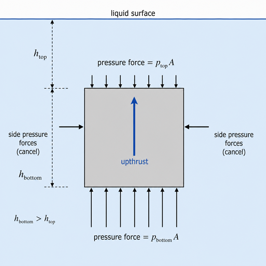
- Consider an object in a liquid. The liquid exerts pressure on every part of the surface.
- The top of the object is at a smaller depth than the bottom .
- Since , we have .
- Force due to pressure on a surface is . So the upward force on the bottom face is
and the downward force on the top face is
- Because , , giving a net upward force.
- Forces on the sides act horizontally in opposite directions and cancel, so the resultant from the liquid is upward: the upthrust.
(At a higher level, this net upthrust is equal to the weight of liquid displaced, i.e. Archimedes’ principle.)
Key Takeaways
- Pressure increases with depth.
- Net upthrust comes from a pressure difference between bottom and top surfaces.
- Side forces cancel.
Common Mistakes
- Saying “pressure pushes up” without mentioning the difference in pressure with depth.
- Forgetting that pressure acts in all directions, so side forces exist but cancel.
Things to Be Careful About
- Use clear language: bottom has greater pressure because it is deeper.
- Distinguish pressure () from force ().
A small steel ball of radius and mass falls vertically at terminal speed through oil.
The viscous drag force that acts on the ball is given by
where is a property of the oil called its viscosity.
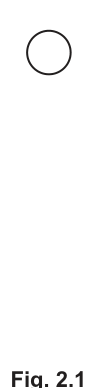
On Fig. 2.1, draw labelled arrows from the ball to show the directions of the three forces that act on the ball as it falls.
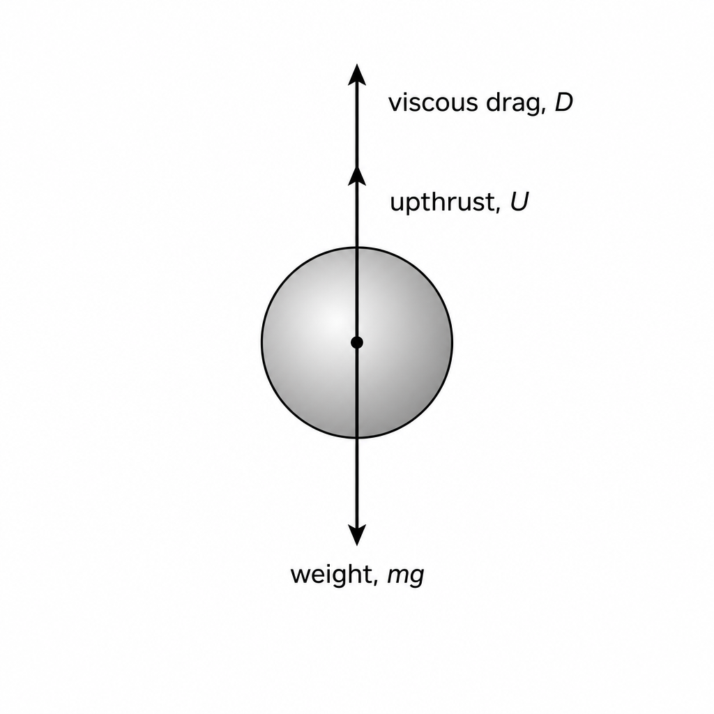
Answer
Weight acts vertically downward.
Upthrust acts vertically upward.
Viscous drag acts vertically upward (opposes the downward motion).
Forces: weight mg downward; upthrust upward; drag D upward.
Background Concept
For an object moving through a fluid:
- Weight acts downward.
- Upthrust (buoyant force) acts upward due to pressure differences in the fluid.
- Drag (resistive force) acts opposite to the direction of motion; here it is viscous drag.
At terminal speed, acceleration is zero, so the resultant force is zero.
Understanding the Question
The ball is falling down through oil at terminal speed. You must draw arrows from the ball showing the directions of the three forces and label them.
Approach
List the forces on a falling sphere in a fluid and set their directions by physical meaning:
- gravity always downward,
- buoyancy always upward,
- drag opposes motion, so upward for downward motion.
Step-by-Step Reasoning
- Weight acts toward the centre of Earth, so draw a downward arrow labelled .
- Upthrust is the net force from fluid pressure, which is upward, so draw an upward arrow labelled “upthrust” (or ).
- Drag opposes the motion. Since the ball moves downward, drag is upward, so draw an upward arrow labelled .
(If you also use the fact that speed is terminal: the two upward forces together balance weight.)
Key Takeaways
- Drag acts opposite to motion.
- Upthrust is always upward in a fluid.
- Weight is always downward.
Common Mistakes
- Drawing drag downward (same direction as motion).
- Missing one of the three forces.
- Labelling upthrust as “pressure” without indicating it is a force.
Things to Be Careful About
- Arrows should start at the ball and point in the correct direction.
- Use clear labels: , , and upthrust ().
Working
From
Units:
Answer
kg m^-1 s^-1
Background Concept
To find SI base units of a quantity, use a given physical equation and ensure dimensional consistency (homogeneity). Constants like have no units.
Useful base-unit facts:
- has units
- has units
Understanding the Question
You are given the drag law for a sphere:
You must determine the SI base units of viscosity .
Approach
Rearrange to make the subject, then replace each quantity by its SI units and simplify to base units (, , , etc.).
Step-by-Step Reasoning
- Rearrange:
- Ignore (dimensionless).
- Substitute units:
- in newtons:
- in metres:
- in
So
- Simplify denominator: .
- Divide:
Key Takeaways
- Rearrange first, then substitute SI units.
- Check that dimensionless constants do not affect units.
Common Mistakes
- Treating as having units.
- Using for pressure-like quantities (viscosity is not pressure).
- Forgetting that includes .
Things to Be Careful About
- Write the final answer in SI base units (not in derived units like N).
- Keep track of negative indices carefully when simplifying.
The oil in (b) has a density of and a viscosity of in SI units.
The steel ball has a mass of and a radius of .
Working
Upthrust equals weight of displaced oil:
Answer
2.8 × 10^-3 N
Background Concept
Archimedes’ principle: the upthrust on an object equals the weight of fluid displaced.
So for a fully immersed object of volume in a fluid of density :
For a sphere of radius :
Understanding the Question
You are given the oil density and ball radius . You must show that the buoyant force (upthrust) on the ball is .
Approach
Compute the sphere’s volume, then multiply by to get the weight of displaced oil.
Step-by-Step Reasoning
- Volume of the ball:
- Evaluate :
- So
- Upthrust:
Key Takeaways
- Upthrust depends on fluid density and displaced volume, not on the object’s mass.
- For a sphere, use .
Common Mistakes
- Using the density of the steel instead of the oil.
- Using diameter instead of radius in .
- Dropping powers of ten when cubing .
Things to Be Careful About
- Keep in metres before calculating volume.
- cubed is (a very common slip).
Working
At terminal speed, resultant force is zero:
Using :
Answer
5.6 × 10^-2 m s^-1
Background Concept
When an object falls through a fluid, three vertical forces act:
- weight downward,
- upthrust upward,
- drag upward (opposes downward motion).
At terminal speed, acceleration is zero, so the resultant force is zero:
The drag is given by
Understanding the Question
You are given , , oil viscosity , and the upthrust from part (i). You must calculate the terminal speed .
Approach
- Use terminal-speed condition to form the force balance.
- Find the drag force needed to balance weight minus upthrust.
- Substitute into and solve for .
Step-by-Step Reasoning
- At terminal speed:
so
- Calculate weight:
- Subtract upthrust :
- Use Stokes’ drag law and rearrange:
- Substitute (SI units), :
Key Takeaways
- Terminal speed means forces balance (not that forces are zero).
- For a falling object: is balanced by (upthrust + drag).
- Rearranging a given formula cleanly is essential for full marks.
Common Mistakes
- Setting and forgetting upthrust.
- Using (wrong sign for upthrust).
- Substituting in mm instead of m.
Things to Be Careful About
- Use consistent SI units: in m, in N, in .
- Terminal speed is a constant speed: acceleration , so resultant force .
- Keep sufficient significant figures during intermediate steps to avoid rounding errors.
A wire has length and cross-sectional area . The wire is made from a metal that has Young modulus and resistivity .
Answer
Young modulus is the ratio of tensile stress to tensile strain (within the limit of proportionality), i.e.
Young modulus is stress/strain (within limit of proportionality).
Background Concept
Young modulus is a measure of how stiff a material is when stretched (or compressed) elastically.
- Tensile stress is force per unit cross-sectional area:
- Tensile strain is fractional extension:
Within the limit of proportionality (the straight-line part of a force–extension graph), stress is proportional to strain, so their ratio is constant and equal to :
Understanding the Question
You are asked to define Young modulus. So you must give the key ratio (stress divided by strain) and state the condition that it applies in the linear elastic region (limit of proportionality).
Approach
Write the standard definition in words or as an equation. For full credit, include “within the limit of proportionality” (or equivalent wording such as “in the elastic region where Hooke’s law applies”).
Step-by-Step Reasoning
- Identify the quantity being defined: Young modulus .
- Recall the definition:
- Add the condition: this is valid where the stress–strain relationship is linear (limit of proportionality).
Key Takeaways
- Stress is and strain is .
- Young modulus is their ratio in the linear elastic region.
Common Mistakes
- Writing (inverted).
- Missing the condition “within the limit of proportionality”.
- Confusing Young modulus with spring constant (property of an object, not the material).
Things to Be Careful About
- Use “stress” and “strain” explicitly; “force/extension” is not the same as .
- State the region of validity (limit of proportionality / Hooke’s law region).
State an expression, in terms of some or all of , , and , for the resistance of the wire.
= ______
Answer
R0 = \rho L / A
Background Concept
For a uniform wire of length and cross-sectional area , the resistance is related to the material property resistivity by
This comes from the microscopic model of resistance and is an experimentally established relation for ohmic conductors at constant temperature.
Understanding the Question
The question asks for the resistance of the unstretched wire, expressed using the given symbols , , , and . Only , and are needed for resistance.
Approach
Recall the standard resistivity equation for a wire and write it using the symbols provided.
Step-by-Step Reasoning
- Start with
- For the original (unstretched) wire, label this resistance :
Key Takeaways
- is a property of the material.
- Geometry matters: and .
Common Mistakes
- Using (inverted).
- Including unnecessarily.
- Forgetting that has units .
Things to Be Careful About
- The formula assumes uniform cross-section and constant temperature.
- Use (area), not radius or diameter directly unless you convert first.
Working
So
Answer
k0 = EA/L
Background Concept
There are two connected descriptions of stretching:
- Material description (Young modulus):
- Object description (Hooke’s law / spring constant): for a wire behaving elastically,
where is the extension.
The spring constant depends on the object’s dimensions as well as the material.
Understanding the Question
You must show that a wire (length , area ) made of a material with Young modulus behaves like a spring with spring constant
So you need to connect to and extension and then identify .
Approach
- Write stress as .
- Write strain as .
- Substitute into .
- Rearrange into the Hooke’s law form .
Step-by-Step Reasoning
- Start from Young modulus:
- Substitute stress and strain:
So
- Simplify the complex fraction by multiplying top and bottom:
- Rearrange to make the subject:
- Compare with Hooke’s law . Therefore
Key Takeaways
- links stress and strain; links force and extension.
- A longer wire is less stiff ().
- A thicker wire is stiffer ().
Common Mistakes
- Using strain as instead of .
- Forgetting the cross-sectional area in stress.
- Writing (missing ).
Things to Be Careful About
- This result assumes extension is small and within the limit of proportionality.
- Use (or ) consistently as the extension, not the total length.
The wire is stretched, within the limit of proportionality, by a tensile force . Assume that any changes in the cross-sectional area of the wire are negligible.
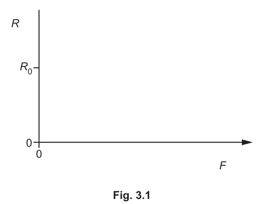
Answer
As increases (within the limit of proportionality), the length increases so increases.
Sketch: straight line with positive gradient passing through at .
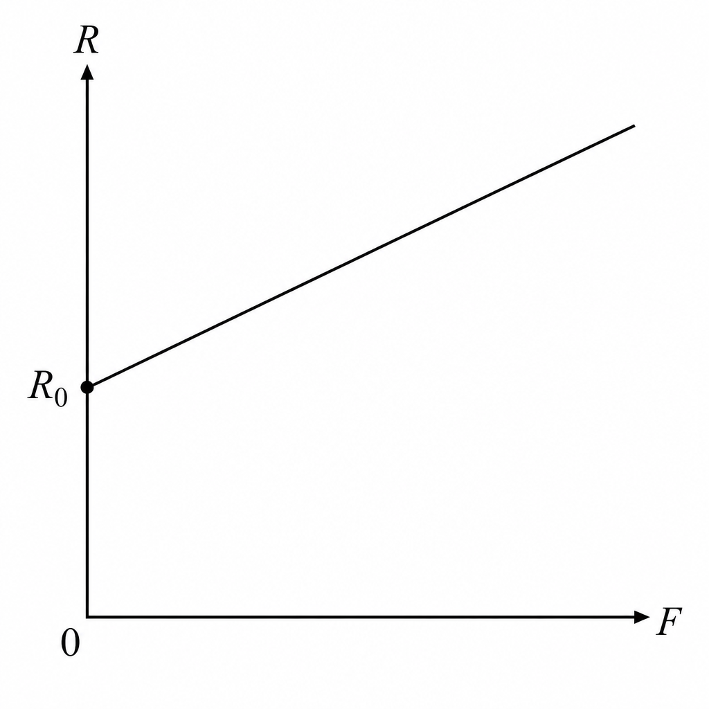
Straight line increasing from R0 at F = 0.
Background Concept
The resistance of a uniform wire is
Here is the resistivity (assumed constant) and the question says changes in cross-sectional area are negligible, so is constant.
Within the limit of proportionality, the extension is proportional to the applied force (Hooke’s law behaviour):
So the new length is , and therefore resistance changes because changes.
Understanding the Question
You are asked to sketch how the wire’s resistance varies as the tensile force increases, starting from the original resistance at .
Key clues:
- “within the limit of proportionality” (\Rightarrow x \propto F)
- “changes in cross-sectional area negligible” (\Rightarrow A \text{ constant})
Approach
- Use .
- As the wire stretches, replace by .
- Since , the resistance should increase linearly with .
Step-by-Step Reasoning
- Initially, at , the wire has length and resistance
- Apply force . The wire extends by (small and elastic), so the length becomes
- New resistance:
So
- Within the limit of proportionality, , so increases in direct proportion to :
So the graph of against is a straight line starting at and rising.
Key Takeaways
- If is constant, stretching increases and therefore increases .
- In the Hooke’s law region, extension is proportional to force, giving a linear graph.
Common Mistakes
- Drawing the line through the origin (it must pass through when ).
- Drawing a curve (with the given assumptions, it is linear).
- Making decrease (resistance increases with length).
Things to Be Careful About
- The question tells you to neglect changes in . If were to decrease significantly, would increase more strongly, but that is not required here.
- Resistivity can change with temperature, but there is no mention of heating; assume constant.
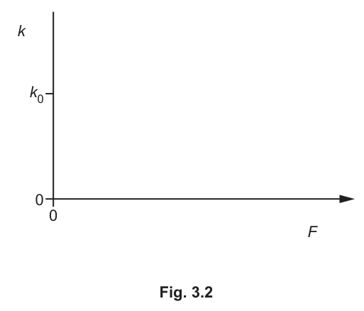
Answer
As increases, the wire length increases, so
decreases from .
Sketch: a decreasing curve starting at when .
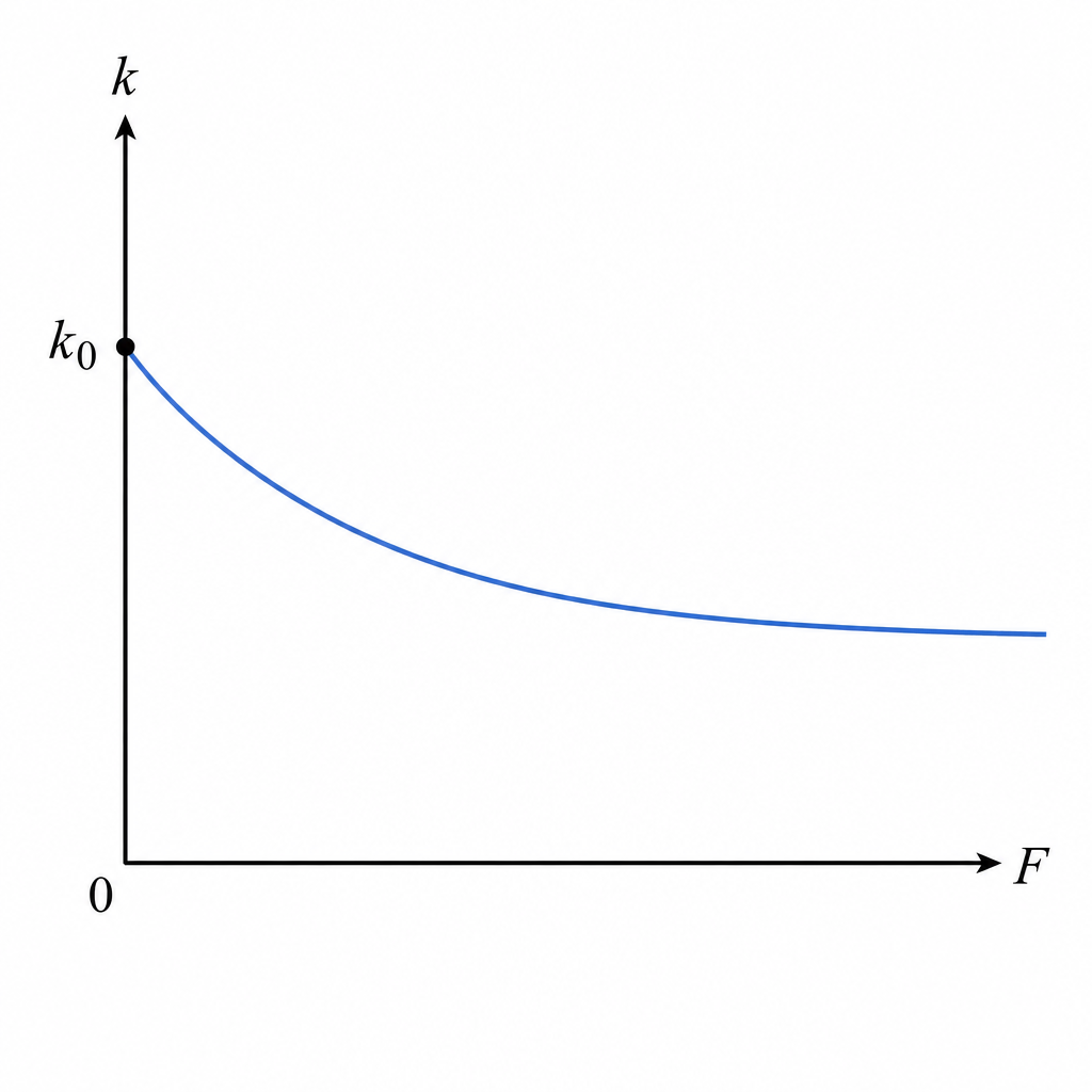
k decreases from k0 as F increases (decreasing curve).
Background Concept
For a wire behaving elastically,
and for a uniform wire (material Young modulus , cross-sectional area , length ):
This shows stiffness depends on current length: a longer wire is less stiff.
Understanding the Question
You are asked to sketch how the spring constant changes as the tensile force increases, given that the wire is stretched within the limit of proportionality and area changes are negligible.
The key point is that as you increase , the wire extends, so its length is no longer the original ; it becomes .
Approach
- Use the result but apply it to the stretched length .
- Since increases with , must decrease with .
- Optionally, use Hooke’s law to show the dependence is not linear.
Step-by-Step Reasoning
- Initially, at , the wire length is and the spring constant is
- When a force is applied (still in the proportional region), the wire extends by , so
- The spring constant corresponding to length is
-
As increases, increases, so the denominator increases and therefore decreases.
-
If you want the shape: within the proportional region,
So
and hence
That is a decreasing curve (it flattens as increases), starting at when .
Key Takeaways
- For a wire, stiffness is inversely proportional to its length.
- Stretching increases length, so the wire becomes less stiff as it is pulled.
Common Mistakes
- Drawing as constant at (only true if the length remained exactly ).
- Drawing increasing with .
- Drawing a straight-line decrease through the origin (it must start at at ).
Things to Be Careful About
- The wire is within the limit of proportionality, so the material is not permanently deformed; however, the geometry still changes while the force is applied.
- You are told to neglect changes in , so only changes in .
Copper has a resistivity of and a Young modulus of .
A copper wire of diameter has a resistance of .
Working
Diameter so radius .
Using
Answer
3.8 m
Background Concept
For a uniform wire,
where:
- is resistance in ,
- is resistivity in ,
- is length in ,
- is cross-sectional area in .
For a circular cross-section,
Understanding the Question
You are given:
- ,
- diameter ,
- resistance .
You must show the wire length is .
Approach
- Convert diameter to metres and find radius.
- Compute area .
- Rearrange to .
- Substitute and evaluate carefully with powers of ten.
Step-by-Step Reasoning
- Convert and find radius:
- Area:
- Rearrange resistivity equation:
- Substitute:
Compute the powers of ten and numbers separately:
So
Key Takeaways
- Always convert mm to m before using SI equations.
- For circular wires, area comes from radius squared.
- Rearranging is standard for these problems.
Common Mistakes
- Using diameter instead of radius in .
- Forgetting to convert to (gives an answer off by ).
- Rearranging to (incorrect).
Things to Be Careful About
- Keep enough significant figures during intermediate steps to reach .
- Track powers of ten explicitly when dividing by .
Use the equation in (b)(ii) to determine the spring constant of the wire.
spring constant = ______
Working
Answer
6.9 × 10^4 N m^-1
Background Concept
A wire in elastic tension behaves like a spring. Its spring constant is
where:
- is Young modulus (),
- is cross-sectional area (),
- is wire length ().
This result comes from combining with .
Understanding the Question
You are told to use the equation from (b)(ii) and the wire data:
- ,
- diameter (so you must find ),
- length from (d)(i).
You must calculate the spring constant in .
Approach
- Find from the diameter.
- Substitute into .
- Check units: ; dividing by gives .
Step-by-Step Reasoning
- Radius:
- Area:
- Substitute into :
Compute first:
Then divide by :
Key Takeaways
- Spring constant of a wire increases with and , decreases with .
- Unit-checking helps confirm the result is sensible.
Common Mistakes
- Using diameter as radius when finding .
- Using in cm or mm instead of m.
- Writing units as instead of .
Things to Be Careful About
- Keep consistent SI units throughout.
- Use the length found in (d)(i); do not re-calculate with a rounded area in a different way that changes the final significant figures.
Answer
Diffraction is the spreading of a wave as it passes through a gap (or around an obstacle/edge), into the region of geometrical shadow.
Diffraction is the spreading of a wave as it passes through a gap (or around an obstacle/edge), into the region of geometrical shadow.
Background Concept
Diffraction is a wave behaviour that occurs because different parts of a wavefront can act as sources of secondary wavelets (Huygens’ principle). When a wave encounters an aperture or an edge, the wavefront is interrupted and the wave energy can spread out into directions that would not be predicted by straight-line (ray) ideas.
Understanding the Question
You are asked to state what “diffraction of a wave” means. This is not asking for conditions (like gap size comparable to wavelength), but the meaning/description of the effect.
Approach
Give a concise definition describing what happens to a wave when it meets an aperture or obstacle: it spreads/bends into the shadow region.
Step-by-Step Reasoning
- A wave travelling in a straight direction meets a gap or edge.
- Beyond the gap/edge, the wavefront does not remain a straight, narrow beam.
- Instead, the wave spreads out (diffracts) into surrounding space, including into the region where rays would predict no wave.
Key Takeaways
- Diffraction is wave spreading at gaps/edges.
- Mentioning the “shadow region” is a strong defining phrase.
Common Mistakes
- Stating only “bending” without mentioning spreading.
- Describing interference patterns rather than defining diffraction.
Things to Be Careful About
- Keep it general: it applies to any wave (sound, water, light).
- Don’t confuse diffraction with refraction (change of direction due to change of speed in a new medium).
A beam of vertically polarised light of wavelength is incident normally on a diffraction grating, as shown in Fig. 4.1.
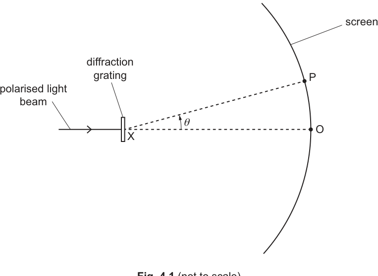
The diffraction grating has a line spacing of .
The light transmitted by the diffraction grating illuminates a circular screen. The diffraction grating is at the centre X of the circle.
The central bright fringe is formed at point O on the screen and has intensity .
P is a point on the screen where the line XP is at a variable angle to the line XO. The intensity of light on the screen at P varies with .
Working
For a diffraction grating,
First order: , , .
Answer
6.2°
Background Concept
A diffraction grating has many equally spaced slits. Bright fringes (principal maxima) occur when waves from adjacent slits interfere constructively. The condition for a principal maximum is that the path difference between adjacent slits equals an integer number of wavelengths:
where:
- is the grating line spacing (distance between adjacent slits),
- is the angle from the straight-through direction (the normal),
- is the order number (),
- is the wavelength.
Understanding the Question
Light of wavelength is incident normally on a grating with spacing . You must show that the first-order () bright fringe occurs at .
Approach
Use the grating equation with . Convert the wavelength from nm to m, calculate , then take to find .
Step-by-Step Reasoning
- Convert wavelength:
- Apply the grating equation for first order ():
- Convert from sine to angle:
This matches the value requested.
Key Takeaways
- Principal maxima angles come from .
- Always convert nm to m in calculations.
Common Mistakes
- Forgetting to convert into metres.
- Using as if it were lines per metre (it is spacing, not line density).
- Using without checking the size of the angle (here it would still be close, but the question expects the proper calculation).
Things to Be Careful About
- Ensure is measured from the central direction (the normal), as in the grating equation.
- Keep significant figures sensible: is given to 2 s.f., so to about 2 s.f. is appropriate.
Working
Second order: .
Answer
12.5°
Background Concept
For a diffraction grating, the th order maximum occurs where the path difference between adjacent slits is , giving:
Higher order () fringes occur at larger angles, as long as .
Understanding the Question
You are asked for the angle of the second-order bright fringe for the same grating and wavelength as in part (b)(i).
Given:
Approach
Substitute into and then take the inverse sine.
Step-by-Step Reasoning
- Compute :
- Find the angle:
Key Takeaways
- Doubling the order roughly doubles (not itself).
- Check to ensure the order exists.
Common Mistakes
- Writing (not generally correct because of the sine relationship).
- Leaving the answer as rather than calculating .
Things to Be Careful About
- Use degrees (as the axis and question specify).
- Don’t round too early; keep enough figures in before applying .
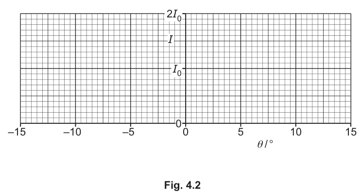
Answer
Sketch sharp principal maxima at
- with height ,
- (first order),
- (second order),
with the pattern symmetric about and intensity close to zero between maxima. The first- and second-order peaks should be shown smaller than the central peak.
Sharp symmetric maxima at 0°, ±6.2°, ±12.5°; central peak I0; others smaller; near-zero between.
Background Concept
A diffraction grating produces a set of very narrow bright fringes (principal maxima) at angles that satisfy:
Because there are many slits, the maxima are sharp and the intensity between them is very low. The pattern is symmetric: for every maximum at there is a corresponding maximum at .
In real gratings, higher orders often have lower intensity (due to slit diffraction envelope and grating efficiency), so a sketch typically shows the central maximum largest, then decreasing heights for , then .
Understanding the Question
You must sketch against from to .
From earlier parts:
- maximum at with intensity (given).
- maxima at .
- maxima at .
No higher orders fit within .
Approach
Mark the angular positions of the allowed orders on the axis, then draw narrow peaks at those positions, making the graph symmetric. Use the given reference level for the central peak and show reduced heights for higher orders.
Step-by-Step Reasoning
- Place the central maximum at and label its height as .
- Add first-order maxima at and .
- Add second-order maxima at and .
- Draw these as sharp (narrow) peaks, because a grating produces sharp principal maxima.
- Make the intensity between peaks close to zero.
- Show decreasing peak heights for increasing order (central largest; first order smaller; second order smaller again).
Key Takeaways
- Grating maxima occur at discrete angles given by the grating equation.
- The pattern must be symmetric about .
- Many slits produce narrow maxima and low intensity between them.
Common Mistakes
- Putting peaks at the wrong angles (e.g. using and but not symmetric, or forgetting negative angles).
- Drawing broad sinusoidal oscillations rather than sharp grating maxima.
- Making the first/second order peaks larger than the central maximum without any justification.
Things to Be Careful About
- The sketch is qualitative, but peak positions must be correct.
- Use the provided marking correctly: the central peak should reach .
- Stay within the stated range to (so do not add third order).
A polarising filter is placed in the path of the light beam that is incident on the diffraction grating in Fig. 4.1. The transmission axis of the filter is at to the vertical.
Suggest how the variation of intensity with for the light on the screen compares with the answer in (b)(iii).
Answer
The polariser at transmits intensity
So the diffraction pattern has maxima at the same angles as in (b)(iii), but all intensities (including the central maximum) are reduced by a factor of (central becomes ).
Same fringe angles as (b)(iii), but all intensities are halved (central becomes I0/2).
Background Concept
A polarising filter transmits only the component of the electric field along its transmission axis. If plane-polarised light of intensity is incident on a polariser whose axis makes an angle with the light’s polarisation direction, Malus’s law gives the transmitted intensity:
A diffraction grating determines the angles of the bright fringes through the interference condition , which depends on , and , not on the intensity.
Understanding the Question
Originally the light is vertically polarised. A polariser with axis at to the vertical is inserted before the grating. You must compare the new vs graph with the sketch in (b)(iii).
Approach
- Use Malus’s law with to find the factor by which the incident intensity is reduced.
- State that diffraction angles (peak positions) are unchanged because is unchanged.
- Therefore the whole intensity pattern is scaled down by the same factor.
Step-by-Step Reasoning
- The incident light is vertically polarised; the filter axis is at to vertical, so the angle between them is .
- Apply Malus’s law:
- The grating still has the same , and the light still has the same wavelength , so the maxima angles from
are unchanged.
- Because the light entering the grating is half as intense, every bright fringe on the screen is correspondingly reduced in intensity by a factor of . In particular, the central maximum changes from to .
Key Takeaways
- Malus’s law changes intensity, not wavelength.
- Diffraction/interference geometry sets positions of fringes; intensity sets heights.
Common Mistakes
- Saying the fringe angles change (they do not, since and are unchanged).
- Using instead of for intensity.
- Claiming the light becomes unpolarised after the filter (it remains plane-polarised along the filter axis).
Things to Be Careful About
- The reference in part (b) refers to the original central maximum; after inserting the polariser the central maximum is .
- The overall shape (peak positions and relative distribution) stays the same; it is a uniform vertical scaling of the graph.
Answer
At any junction, the total current entering equals the total current leaving (algebraic sum of currents at a junction is zero).
At any junction, the total current entering equals the total current leaving (algebraic sum of currents at a junction is zero).
Background Concept
Kirchhoff’s first law is a statement of conservation of charge in an electric circuit. Charge cannot be created or destroyed at a junction, so charge per unit time (current) must be conserved.
If several currents meet at a node (junction), then the rate at which charge arrives must equal the rate at which charge leaves.
Understanding the Question
You are asked to state Kirchhoff’s first law, so you need a single clear sentence describing the relationship between currents at a junction.
Approach
Write the law in one of the accepted equivalent forms:
- “sum entering = sum leaving”, or
- “algebraic sum of currents at a junction is zero”.
Step-by-Step Reasoning
- Current is charge flow rate: .
- At a junction, the charge that flows in per second must equal the charge that flows out per second (otherwise charge would build up at the junction).
- Therefore the total current entering the junction equals the total current leaving the junction.
Key Takeaways
- Kirchhoff’s first law is conservation of charge applied to circuit junctions.
- It relates currents, not voltages.
Common Mistakes
- Stating Kirchhoff’s second law (sum of p.d.s around a loop) instead of the first.
- Saying “currents are equal” without specifying entering equals leaving at a junction.
Things to Be Careful About
- Use the word junction/node.
- Mention entering and leaving (or use “algebraic sum is zero”) to avoid ambiguity.
Fig. 5.1 shows a circuit containing a thermistor T that has a negative temperature coefficient.
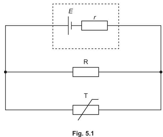
The thermistor has resistance at a temperature of .
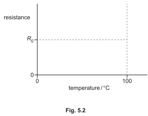
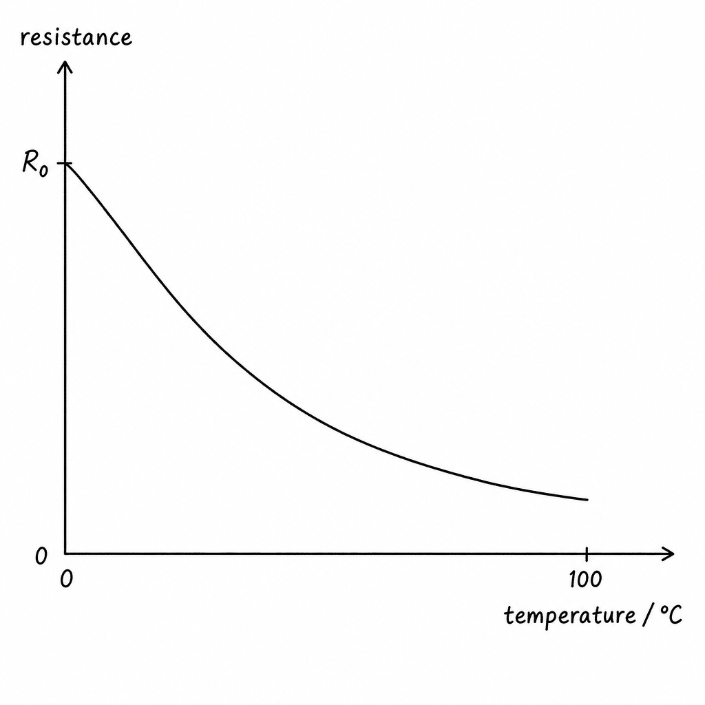
On Fig. 5.2, sketch a possible variation of the resistance of the thermistor with temperature between and .
Answer
A decreasing (non-linear) curve starting at when and falling to a smaller resistance at .
A decreasing (non-linear) curve from R0 at 0°C to a smaller resistance at 100°C.
Background Concept
A thermistor with a negative temperature coefficient (NTC) has resistance that decreases as temperature increases.
This happens because, in a semiconductor thermistor, increasing temperature increases the number of charge carriers, so conductivity increases and resistance falls. The fall is typically non-linear (often roughly exponential).
Understanding the Question
You are told the thermistor has resistance at , and you must sketch how its resistance changes up to . The axes already show the point corresponding to on the resistance axis.
Approach
- Start the graph at .
- Because it is NTC, the curve must go downwards as temperature increases.
- Make it curved (not a straight line) to show a “possible variation”.
Step-by-Step Reasoning
- Mark the point at with resistance .
- For higher temperature, resistance must be less than , so the graph must slope downwards to the right.
- Draw a smooth non-linear curve decreasing towards (for many NTC thermistors it falls steeply at first and then becomes less steep).
Key Takeaways
- NTC thermistor: higher (\Rightarrow) lower resistance.
- Sketch should pass through and decrease to the right.
Common Mistakes
- Drawing resistance increasing with temperature (that would be PTC, not NTC).
- Not starting the curve at the marked value at .
- Drawing a horizontal line (implies resistance constant).
Things to Be Careful About
- The question says “possible variation”, so exact shape is not required, but it must clearly be decreasing and should be smooth.
- Keep axes labels consistent: resistance on -axis, temperature on -axis.
With reference to the current in the cell, explain why the current in resistor R decreases with increasing temperature of the thermistor.
Answer
As temperature increases, the thermistor resistance decreases, so the equivalent resistance of the parallel combination decreases and the current in the cell increases.
With internal resistance , the lost p.d. increases, so the terminal p.d. across the parallel network (and hence across ) decreases.
Since , a smaller p.d. across means the current in decreases.
Thermistor resistance falls → total cell current rises → larger Ir drop across internal resistance → smaller terminal p.d. across R → IR decreases.
Background Concept
There are two key ideas:
- Parallel resistance: if two resistors are in parallel, the equivalent resistance satisfies
So if the thermistor resistance decreases, also decreases.
- Internal resistance: a cell with e.m.f. and internal resistance behaves like an ideal source in series with a resistor . If the cell current is , then terminal p.d. is
So as increases, the “lost volts” increases and decreases.
Understanding the Question
The circuit has the cell (with internal resistance) feeding a parallel network of a fixed resistor and an NTC thermistor .
You must explain why the current in resistor decreases when the thermistor temperature increases, and you must refer to the current in the cell in your explanation.
Approach
Chain the cause-and-effect:
- Increase thermistor temperature (\Rightarrow) thermistor resistance decreases (NTC).
- Lower thermistor resistance (\Rightarrow) lower equivalent resistance of the parallel part.
- Lower external resistance (\Rightarrow) larger current drawn from the cell.
- Larger cell current (\Rightarrow) bigger voltage drop across internal resistance .
- Bigger internal drop (\Rightarrow) smaller terminal p.d. across the parallel part, so smaller p.d. across .
- With fixed, smaller p.d. (\Rightarrow) smaller current in .
Step-by-Step Reasoning
- The thermistor is NTC, so when temperature increases, its resistance decreases.
- The thermistor is in parallel with , so decreasing decreases the equivalent resistance of the parallel pair.
- The cell sees a smaller external resistance, so the current drawn from the cell increases.
- Because the cell has internal resistance , there is a lost p.d. inside the cell. When increases, increases.
- Therefore the terminal p.d. across the parallel network is
and this terminal p.d. decreases as increases.
6. The resistor is connected directly across this terminal p.d., so .
7. Since is constant, the current through it is
so when decreases, decreases.
(You may also note that in parallel, a smaller thermistor resistance “steals” more current; however, the key reason decreases is that the voltage across falls due to the increased internal drop.)
Key Takeaways
- NTC thermistor: higher gives lower .
- Lower external resistance increases cell current.
- With internal resistance, higher cell current reduces terminal p.d., reducing branch currents.
Common Mistakes
- Claiming the p.d. across stays constant; it does not when the cell has internal resistance.
- Saying “current splits so decreases” without mentioning the required link to cell current and lost volts.
- Forgetting that is in parallel, so the p.d. across equals the terminal p.d.
Things to Be Careful About
- Use correct language: “terminal p.d.” is across the external circuit; “lost p.d.” is across internal resistance.
- Do not confuse (cell current) with (current in resistor ).
The electromotive force (e.m.f.) of the cell in Fig. 5.1 is . The internal resistance of the cell is .
Resistor R has a resistance of .
At a particular temperature of the thermistor, the current in R is .
For this temperature of the thermistor, determine:
Working
Voltage across :
Lost p.d. across :
Cell current:
Answer
2.50 A
Background Concept
For a cell of e.m.f. and internal resistance , the terminal p.d. when a current flows is
The quantity is the “lost volts” across the internal resistance.
In a parallel network, the p.d. across each branch is the same. So the p.d. across resistor equals the terminal p.d. across the parallel combination.
Understanding the Question
You are given:
- current in is
You must find the current in the cell (the total current supplied to the parallel combination).
Approach
- Use to find the p.d. across .
- That same p.d. is the terminal p.d. of the cell.
- Use to find .
Step-by-Step Reasoning
- Find the p.d. across resistor using Ohm’s law:
- Because is in parallel with the thermistor, the p.d. across the parallel network is also . This is the terminal p.d. of the cell:
- The lost volts across internal resistance are:
- Solve for the cell current:
Key Takeaways
- Use a known branch current to get the terminal p.d. in a parallel circuit.
- Then use to link terminal p.d. to the cell current.
Common Mistakes
- Treating as the p.d. across (it is the e.m.f., not the terminal p.d.).
- Forgetting that the terminal p.d. is reduced by the internal resistance.
Things to Be Careful About
- Keep clear which current is which: is not the cell current.
- Use consistent significant figures: here is appropriate.
Working
Terminal p.d. across the parallel network:
From (i), . Hence thermistor current:
Thermistor resistance:
Answer
0.522 Ω
Background Concept
In a parallel circuit:
- The p.d. across each branch is the same.
- The total current is the sum of the branch currents (Kirchhoff’s first law):
Once you know the p.d. across a component and the current through it, you can find its resistance using Ohm’s law:
Understanding the Question
At the stated thermistor temperature you know:
- current in resistor is
- from part (i) the current in the cell is
You must find the thermistor resistance at that temperature.
Approach
- Find the terminal p.d. across the parallel network using .
- Use Kirchhoff’s first law to get thermistor current .
- Use .
Step-by-Step Reasoning
- The p.d. across is
This is also the p.d. across the thermistor because they are in parallel.
- The total current from the cell is the sum of branch currents:
So
- Apply Ohm’s law to the thermistor:
Key Takeaways
- In parallel: same p.d., currents add.
- Use branch current + p.d. to find branch resistance.
Common Mistakes
- Using as the p.d. across the thermistor (ignoring internal resistance).
- Subtracting currents the wrong way round (getting a negative or tiny thermistor current).
- Using instead of .
Things to Be Careful About
- Ensure you use the terminal p.d. (), not the e.m.f.
- Keep enough significant figures in intermediate steps; round at the end to (3 s.f.).
The nuclide is an isotope of hydrogen that is called tritium.
Determine the numbers of protons, neutrons and electrons in a neutral atom of tritium.
number of protons = ______
number of neutrons = ______
number of electrons = ______
Answer
For :
- number of protons
- number of neutrons
- number of electrons (neutral atom)
protons = 1, neutrons = 2, electrons = 1
Background Concept
A nuclide written as has:
- proton number (atomic number) = number of protons in the nucleus.
- nucleon number (mass number) = total number of nucleons in the nucleus = protons + neutrons.
So:
For a neutral atom, total positive charge from protons is balanced by electrons, so:
Understanding the Question
You are told the nuclide is tritium, . The question asks for the number of protons, neutrons and electrons in a neutral atom (so it includes the electrons outside the nucleus).
Approach
- Read from the subscript to get protons.
- Use to get neutrons.
- Use neutrality (electrons = protons) to get electrons.
Step-by-Step Reasoning
From :
- protons .
- , so neutrons .
- Neutral atom means electrons .
Key Takeaways
- In , gives protons and gives neutrons.
- Neutral atoms have equal numbers of protons and electrons.
Common Mistakes
- Using as the number of neutrons (it is total nucleons).
- Forgetting the word “neutral” and giving electrons (that would be the nucleus, not the atom).
Things to Be Careful About
- Protons and neutrons are in the nucleus; electrons are outside.
- Always subtract in the correct order: neutrons , not .
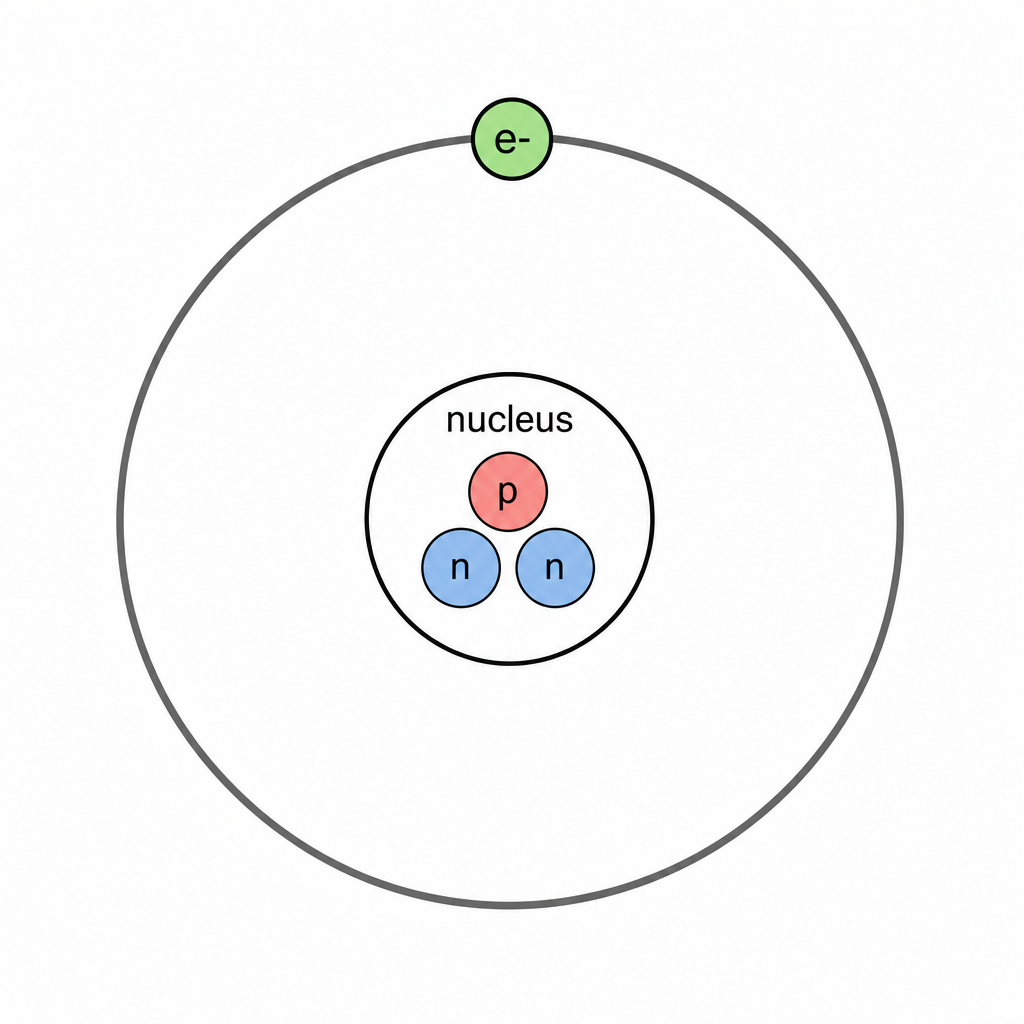
Draw a labelled diagram to represent a simple model of the arrangement of the protons, neutrons and electrons in a tritium atom.
Answer
Nucleus contains and ; electron shown outside the nucleus (in a shell/orbit), with all particles labelled.
Labelled model showing nucleus (1p, 2n) and one electron outside.
Background Concept
A simple atomic model for A Level typically shows:
- a tiny central nucleus containing protons (, charge ) and neutrons (, charge ),
- electrons (, charge ) arranged outside the nucleus (often drawn as shells/orbits for a simple model).
This is not a scale drawing; it is a schematic that shows arrangement and types of particles.
Understanding the Question
You must draw a labelled diagram for tritium. From you know the nucleus has 1 proton and 2 neutrons, and (neutral atom) there is 1 electron outside the nucleus.
Approach
- Draw a central nucleus (circle).
- Put symbols for the correct number of nucleons inside: one and two .
- Draw one electron on an orbit/shell outside.
- Label each particle type clearly.
Step-by-Step Reasoning
- The nucleus is drawn at the centre.
- Inside it, include three nucleons: one labelled (or ) and two labelled .
- Outside, show one electron labelled on a circular shell/orbit.
- Ensure labels identify particle types (and ideally charges).
Key Takeaways
- Nucleons (protons and neutrons) are in the nucleus.
- A neutral atom has the same number of electrons as protons.
- A diagram mark is usually for correct placement and clear labels.
Common Mistakes
- Drawing three electrons because .
- Putting electrons inside the nucleus.
- Not labelling the particles (loses the “labelled diagram” mark).
Things to Be Careful About
- The diagram is a model: not to scale, but the nucleus must be shown as central with electrons outside.
- Count particles correctly: tritium has electron total (not 2 or 3).
Tritium is radioactive and undergoes decay to form an isotope of helium (He). Gamma radiation is not emitted during this decay.
Working
Conserve nucleon number and proton number .
Answer
and .
${}^3_2\text{He} + {}^0_{-1}\beta
Background Concept
In nuclear decay equations, two conservation rules are essential:
- Nucleon number is conserved.
- Proton number (equivalently nuclear charge) is conserved.
In decay, inside the nucleus a neutron changes into a proton and emits:
- an electron (the particle), and
- an electron antineutrino to conserve lepton number and energy-momentum.
So increases by 1 while stays the same.
Understanding the Question
Tritium is . It undergoes decay to become an isotope of helium. You must fill in the missing nuclide numbers for He and for the particle in the equation (gamma not emitted). The equation already includes a particle X with .
Approach
- Use the rule for decay: unchanged, increases by 1 for the daughter nucleus.
- Write the daughter nucleus as helium with the found and .
- Use standard notation for a beta-minus particle: .
- Check conservation of and across the full equation.
Step-by-Step Reasoning
Start with parent:
- , .
After decay:
- stays .
- increases to .
So the daughter nucleus is:
A particle is an electron, written:
Now check balancing:
- Nucleon number: LHS ; RHS .
- Proton number: LHS ; RHS .
So the completed equation is consistent.
Key Takeaways
- In decay: unchanged, increases by 1.
- A particle is written as .
Common Mistakes
- Writing helium as (forgetting must increase).
- Using (that would be / positron emission).
- Changing in decay (it does not change).
Things to Be Careful About
- Use the correct nuclear notation with superscript/subscript.
- Remember that the antineutrino has (so it does not affect or balancing).
Answer
Particle is an electron antineutrino, .
electron antineutrino
Background Concept
In decay, a neutron in the nucleus transforms as:
The emitted electron is the particle. The electron antineutrino is required to conserve lepton number and also helps account for the energy/momentum distribution in the decay.
Understanding the Question
The decay equation includes an unknown particle written with , meaning it has no nucleon number and no charge. You are asked to state its name.
Approach
Recognise the decay is decay and recall the standard particles emitted: electron and electron antineutrino.
Step-by-Step Reasoning
- emission produces an electron.
- The accompanying neutral, very small-mass particle in the equation is the electron antineutrino.
Therefore:
Key Takeaways
- decay emits an electron and an electron antineutrino.
- The antineutrino has in nuclear-equation notation.
Common Mistakes
- Saying “neutrino” rather than antineutrino (the sign matters for lepton number).
- Answering “gamma” even though the question states gamma is not emitted.
Things to Be Careful About
- Use the full name: electron antineutrino (not muon neutrino, etc.).
- The symbol should be ; the bar indicates antiparticle.
Working
Tritium nucleus: proton and neutrons.
Proton: .
Neutron: .
Total quarks:
- up:
- down:
Answer
Quark composition: .
4 up quarks and 5 down quarks
Background Concept
Protons and neutrons are baryons made of three quarks:
- proton: (two up quarks and one down quark)
- neutron: (one up quark and two down quarks)
A nucleus is made from protons and neutrons, so its total quark content is found by counting how many protons/neutrons it has and adding their quark compositions.
Understanding the Question
You are asked for the quark composition of the tritium nucleus (not the whole atom). Tritium is so its nucleus contains 1 proton and 2 neutrons.
Approach
- Use to find protons () and neutrons ().
- Replace each proton with and each neutron with .
- Add up total numbers of and quarks.
Step-by-Step Reasoning
From :
- protons
- neutrons
Quark content:
- 1 proton contributes , .
- 2 neutrons contribute , .
Totals:
- up quarks:
- down quarks:
So the tritium nucleus contains and .
Key Takeaways
- Proton is ; neutron is .
- Find numbers of protons/neutrons first, then sum quarks.
Common Mistakes
- Counting electrons as having quark composition (electrons are leptons, not made of quarks).
- Using the wrong quark content for proton/neutron (swapping them).
- Forgetting there are two neutrons in tritium.
Things to Be Careful About
- The question specifies nucleus, so only protons + neutrons.
- Present the final answer clearly as totals (e.g. “ up and down”).