Physics 9702/37 — May/June 2025
Cambridge AS Level · Advanced Practical Skills · worked solutions for every part, with the mark scheme
Topics Manipulation, Measurement and Observation · Presentation of Data and Observations · Analysis, Conclusions and Evaluation
In this experiment, you will investigate an electrical circuit.
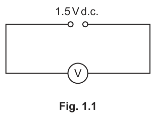
Answer
Record from the voltmeter (e.g. , to the voltmeter resolution).
E ≈ 1.50 V
Background Concept
A voltmeter measures potential difference (p.d.) between two points in a circuit. It must be connected in parallel with the component (or supply) whose p.d. is being measured. The reading is in volts, .
Understanding the Question
You are given a circuit with a d.c. supply and a voltmeter connected across it. You must read the voltmeter to obtain , the supply p.d.
Approach
- Build the circuit exactly as shown.
- Ensure the voltmeter is across the supply.
- Read and record the steady value of with sensible precision.
Step-by-Step Reasoning
- Connect the voltmeter in parallel with the d.c. source as in Fig. 1.1.
- Wait for the reading to settle.
- Record to the resolution of the meter (typically for a digital meter).
Key Takeaways
- Voltmeters measure p.d. and are connected in parallel.
- Record measurements to the instrument resolution with units.
Common Mistakes
- Connecting the voltmeter in series.
- Recording with no unit.
- Over-rounding (e.g. writing if the meter reads to ).
Things to Be Careful About
- Polarity: a reversed voltmeter may show a negative sign.
- Keep the circuit as in the diagram so corresponds to the supply p.d.
You have been provided with a metre rule with a wire attached. You have also been provided with two identical resistors placed in component holders, each labelled R.
Set up the circuit shown in Fig. 1.2.
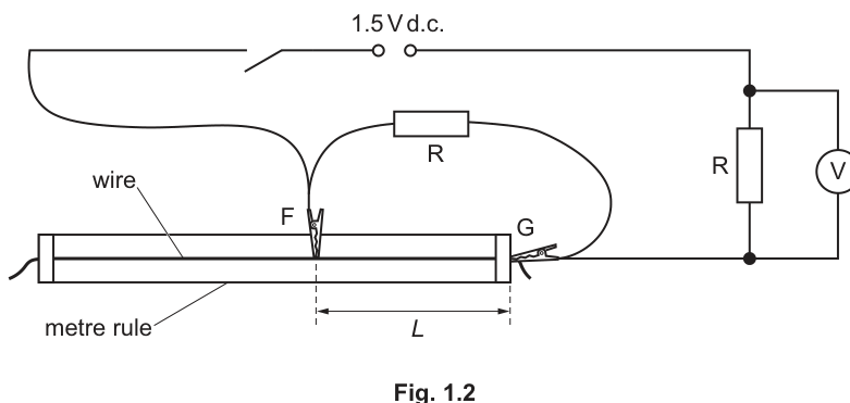
F and G are crocodile clips.
The distance between F and G is . Attach F and G to the wire so that is approximately 30 cm.
Close the switch.
Record the value of and the voltmeter reading .
= ______
= ______
Open the switch.
Answer
Attach clips so that , close the switch, then record and (e.g. , ).
Example: L = 30.0 cm, V = 0.75 V
Background Concept
In practical circuits, changing the effective length of a uniform wire changes its resistance (longer wire larger resistance). A metre rule allows you to set and measure the length between two points accurately. The voltmeter measures the p.d. across the component it is connected across.
Understanding the Question
You must build the circuit in Fig. 1.2 using:
- a wire on a metre rule with crocodile clips and separated by distance ,
- two identical resistors (each labelled ),
- a voltmeter reading .
You then set to about , close the switch, and record and .
Approach
- Assemble the circuit exactly as shown.
- Place and so their separation is about .
- Close the switch briefly, take readings, then open the switch.
Step-by-Step Reasoning
- Use the metre rule scale to set .
- Measure between the clip contact points (not the clip ends).
- Close the switch and allow the voltmeter reading to stabilise.
- Record to the meter resolution and record to the metre rule resolution (often if you estimate between mm marks).
- Open the switch to reduce heating of the wire and resistors.
Key Takeaways
- Measure the separation between contact points for .
- Take steady voltmeter readings and record with units.
Common Mistakes
- Measuring from the wrong points on the crocodile clips.
- Leaving the switch closed for too long, causing heating and drift.
- Recording with inconsistent precision (e.g. sometimes to nearest cm, sometimes to mm).
Things to Be Careful About
- Ensure good electrical contact at and .
- Avoid parallax when reading the metre rule.
- Keep the circuit unchanged except for the intended change in .
Write down the value of from (a).
= ______
Increase by changing the position of F on the wire. Record and and repeat until you have six sets of values of and . Include your values from (b).
Record your results in a table. Include values of in your table.
Answer
(from (a)) = e.g. .
Record six pairs of and (including the value from (b)) and calculate
for each row.
Example of a correctly laid out table (candidate values will differ):
| / | / | / | / |
|---|---|---|---|
Table of 6 readings of L and V with calculated (E−V)/L
Background Concept
Good experimental data needs:
- a clear choice of independent variable (here is changed deliberately),
- a dependent variable to measure (here ),
- enough readings over a sensible range (here six sets),
- clear presentation in a single table with correct headings and units.
When calculating a derived quantity, such as
you should show it in its own column with an appropriate unit. If and are in volts and is in cm, then has unit (or convert to m and use ).
Understanding the Question
You must:
- Write down the same you measured in (a).
- Increase step-by-step (by moving clip ) and for each record the corresponding voltmeter reading .
- Obtain six sets of values in total.
- Present results in a table including a calculated column for .
Approach
- Choose six values of spread over a wide range (e.g. from about up to perhaps depending on the apparatus).
- For each , close the switch briefly, record , then open the switch.
- After the measurements, calculate for each row and enter it into the table.
Step-by-Step Reasoning
- Copy from part (a) exactly (same number of decimal places).
- Set (already done in (b)); record and .
- Increase by moving clip and repeat until you have 6 rows.
- In your table:
- Put all raw and derived data in one table.
- Headings should include quantity and unit, e.g. , , .
- Use consistent decimal places within each column (e.g. to or depending on how you read it; to or depending on meter).
- Calculate each derived value:
using the measured , the measured for that row, and the measured for that row.
Key Takeaways
- Use a single clear table with headings and units.
- Take enough readings over a range.
- Calculated columns must have correct units and consistent precision.
Common Mistakes
- Forgetting to include the row from part (b).
- Writing again but with different rounding to part (a).
- Missing units in the headings.
- Calculating but not stating the unit, or using inconsistent units (mixing cm and m).
Things to Be Careful About
- Keep the switch closed only long enough to take a reading to reduce heating.
- Ensure is the distance between the clip contact points.
- If you convert to m for calculations, be consistent for every row and for your graph later.
Answer
Plot on the -axis (unit e.g. ) against on the -axis (unit ) using all six data points with a suitable scale.
Graph of (E−V)/L (y) against V (x)
Background Concept
A graph is used to reveal relationships between variables. To gain marks, the graph must be readable and accurate:
- correct variables on correct axes,
- clear axis labels including units,
- a sensible scale using at least half of the available grid in each direction,
- points plotted accurately and consistently.
Understanding the Question
You are told exactly what to plot:
- -axis:
- -axis:
using the six sets of values from your table.
Approach
- Decide the numerical ranges of and from your data.
- Choose axis limits and scales that spread points out.
- Plot each point as a small cross (not a dot so large it hides accuracy).
Step-by-Step Reasoning
- From your results table, list the pairs .
- Draw axes with a large plotting area.
- Label axes, for example:
- on the horizontal axis.
- (or if you used m) on the vertical axis.
- Choose a uniform scale (e.g. 1 large square = 0.05 V) that uses most of the grid.
- Plot all six points carefully.
Key Takeaways
- Axes must include both quantity and unit.
- Use a scale that spreads the points for best gradient accuracy.
Common Mistakes
- Swapping axes (plotting on instead of ).
- Missing units in labels.
- Using an awkward scale (e.g. 1 large square = 3 units) that wastes grid space.
Things to Be Careful About
- If you used in cm, keep derived units consistent across the whole graph.
- Plotting accuracy: use a sharp pencil and read to half a small square where possible.
Answer
Draw a single straight line of best fit through the plotted points (with points roughly balanced about the line).
Straight best-fit line drawn
Background Concept
A best-fit line represents the underlying trend in data affected by random uncertainty. For a linear relationship, the best-fit is a straight line that passes as close as possible to all points with an approximately even spread of points above and below.
Understanding the Question
After plotting the points in (d)(i), you must draw the straight line that best represents the trend.
Approach
Use a ruler to draw one straight line that:
- follows the overall trend,
- does not have to pass through every point,
- has roughly equal scatter above and below.
Step-by-Step Reasoning
- Place a ruler so that it lies along the general trend of the plotted points.
- Adjust it so that the vertical distances (residuals) of points above and below are reasonably balanced.
- Draw the line across the full range of your data (not just between two middle points).
Key Takeaways
- Best-fit means balanced scatter, not “join the dots”.
Common Mistakes
- Joining consecutive points with multiple segments.
- Forcing the line through the origin when not justified.
- Drawing a line only through two points rather than fitting all points.
Things to Be Careful About
- Use a sharp pencil and a ruler.
- Extend the line over the plotted range to help later gradient/intercept determination.
Determine the gradient and -intercept of this line.
gradient = ______
-intercept = ______
Working
Choose two well-separated points on the best-fit line, e.g.
and .
Using ,
Answer
gradient
-intercept
gradient ≈ 0.060 cm^-1, y-intercept ≈ −0.020 V cm^-1
Background Concept
For a straight-line graph,
where:
- is the gradient (slope): ,
- is the y-intercept: the value of when .
The most accurate gradient comes from a large triangle using two points on the best-fit line far apart, not necessarily actual data points.
Understanding the Question
You must find:
- the gradient of your best-fit line on the graph of against ,
- the y-intercept of that same line.
Both must be read/calculated using your graph scale and quoted with appropriate units.
Approach
- Pick two points on the best-fit line far apart.
- Compute .
- Find the y-intercept either by reading where the line crosses the y-axis, or by calculating from using a point on the line.
Step-by-Step Reasoning
- Suppose you select two points on the drawn line at convenient grid intersections.
- Compute the changes:
- is the vertical change in .
- is the horizontal change in .
- Divide to get the gradient; the unit is
- Then obtain the y-intercept :
- Either read it at , or calculate it from .
Key Takeaways
- Use a large triangle on the best-fit line for accuracy.
- Gradient units come from “vertical units divided by horizontal units”.
Common Mistakes
- Using two nearby points (large percentage error in gradient).
- Using two data points that are not on the best-fit line.
- Inverting the gradient as .
- Quoting the y-intercept without its sign (many graphs here have a negative intercept).
Things to Be Careful About
- Read values carefully from the scale (half small-square precision where possible).
- Keep the same unit (cm or m) used in the derived column, so your gradient/intercept units match your axes.
It is suggested that the quantities and are related by the equation
where and are constants.
Using your answers in (d)(iii), determine the values of and . Give appropriate units.
= ______
= ______
Working
From the graph, and .
Given
so this is .
Therefore:
- gradient
- y-intercept
Using (d)(iii) (example values):
Answer
P = gradient; Q = −(y-intercept) (with units)
Background Concept
If a graph is plotted as against and the relationship is linear, it can be written as
By comparing with a given physical equation, you can identify constants with:
- gradient ,
- intercept .
Units:
- Here has units (or ).
- has unit .
So has unit and has unit .
Understanding the Question
You are given
and you have already found the gradient and y-intercept of a graph of against . You must use those graph parameters to determine and with units.
Approach
- Map the equation onto .
- Read off as the gradient.
- Use the sign of the intercept carefully: intercept equals .
Step-by-Step Reasoning
Let
Then the given equation becomes
Comparing with :
- ,
- so .
If your y-intercept is negative (common here), then will be positive.
Key Takeaways
- Always rewrite into form to identify constants.
- The y-intercept is the constant term; if the equation has , then the intercept is .
Common Mistakes
- Setting equal to the y-intercept instead of the negative of it.
- Giving or without units.
- Mixing cm and m: if was in cm, use and ; if was in m, use and .
Things to Be Careful About
- Keep signs correct: intercept .
- Quote and to a sensible number of significant figures consistent with graph reading.
The resistance of R is .
Theory suggests that:
- and are both inversely proportional to
- the graph cuts the -axis at a value of for all values of .
A student repeats the experiment using two identical resistors, each with a lower value of than in the original experiment.
For the student's experiment, draw a second line on the graph to show the expected results. Label this line W.
Answer
Since and are inversely proportional to , using a lower gives larger (steeper gradient) and larger (more negative y-intercept because intercept ).
The x-intercept remains at .
Draw line W as a steeper straight line than the original, passing through the same x-intercept , and label it W.
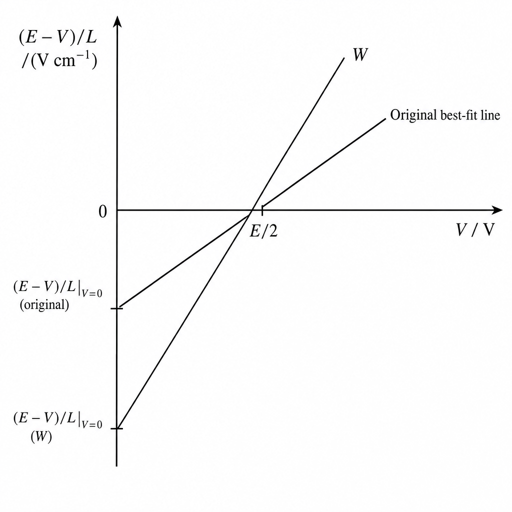
Line W: steeper, same x-intercept at V = E/2
Background Concept
The plotted graph is described by
where and .
- Gradient .
- y-intercept .
- x-intercept occurs when :
You are told that theory predicts:
- and .
- The x-intercept is always at for all .
Understanding the Question
A student repeats the experiment with resistors of LOWER resistance than before. You must predict how the straight line on your vs graph changes, and sketch that new line (labelled W) on the same axes.
Approach
Use the theory statements:
- Lower means both and increase (because they are inversely proportional to ).
- The x-intercept must stay fixed at .
So the new line must rotate about the fixed point .
Step-by-Step Reasoning
- Since is the gradient, increasing makes the line steeper.
- Since the y-intercept is , increasing makes the y-intercept more negative (the line crosses the y-axis lower down).
- Because the x-intercept is fixed at , both the original and new lines must cross the x-axis at the same point.
So W is drawn as a steeper line that still passes through .
Key Takeaways
- Gradient corresponds to and intercept corresponds to .
- If both and scale together, the ratio (and hence the x-intercept) can stay constant.
Common Mistakes
- Shifting the line parallel (keeping the same gradient) instead of making it steeper.
- Moving the x-intercept away from .
- Forgetting that the y-intercept is (so larger means a more negative intercept).
Things to Be Careful About
- The line should be straight and clearly labelled W.
- Ensure it crosses the x-axis at (use your measured value to locate this on your axis scale).
In this experiment, you will investigate the oscillations of a chain of paper clips.
You have been provided with two spheres of modelling clay.
The diameter of the smaller sphere is , as shown in Fig. 2.1.
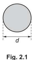
Measure and record .
= ______
Measure the diameter with a ruler.
Example (to nearest ):
d = 2.40 cm (example)
Background Concept
A length measurement should be taken with an instrument of suitable resolution (e.g. ruler, vernier calipers) and recorded to the precision justified by the instrument scale. The measurement uncertainty is linked to the smallest scale division and to how clearly the object edge can be judged.
Understanding the Question
You are asked to measure the diameter of the smaller modelling clay sphere shown. The answer is a direct reading (no calculation). Since the blank gives no unit, you must supply the unit you used (normally or ).
Approach
Use a ruler (or calipers if available): place the sphere against the scale, align one edge with a known mark (often zero), read the other edge, and record the result to appropriate precision. Ensure your eye is directly above the scale to avoid parallax.
Step-by-Step Reasoning
- Place the sphere next to the ruler so that its diameter is aligned with the scale.
- Align one edge of the sphere with a convenient mark (e.g. ) to reduce reading error.
- Read the scale at the opposite edge of the sphere with your eye vertically above the mark.
- Record with a unit and with a sensible number of decimal places for the instrument used (e.g. to the nearest with a ruler).
Key Takeaways
- Record measurements with units and appropriate precision.
- Good alignment and avoiding parallax are essential for accurate readings.
Common Mistakes
- Omitting the unit.
- Writing too many decimal places (not justified by a ruler).
- Parallax error from reading the scale at an angle.
Things to Be Careful About
- If the sphere is slightly squashed or not perfectly spherical, different “diameters” are possible; measure the widest diameter and avoid compressing it while measuring.
- If using a ruler with divisions, a typical reading precision is , so recording to (or is not appropriate here) is important.
Estimate the percentage uncertainty in your value of . Show your working.
percentage uncertainty = ______ %
Using a ruler with divisions, take absolute uncertainty as .
Example with :
percentage uncertainty ≈ 2.1% (example)
Background Concept
Uncertainty in a single length measurement is often taken as about half the smallest scale division (for an analogue scale), because you can usually judge between marks to about that level. Percentage uncertainty is
Understanding the Question
You must estimate the percentage uncertainty in your measured diameter and show the calculation. The percentage uncertainty depends on both the instrument uncertainty and the size of .
Approach
- Decide an absolute uncertainty for based on the instrument (and any difficulty judging the sphere edge).
- Substitute into the percentage uncertainty formula.
Step-by-Step Reasoning
- If a ruler has smallest divisions, a common estimate is for one reading.
- Convert that to the same unit as (e.g. ).
- Divide by your measured and multiply by .
For example, with :
Key Takeaways
- Always use consistent units when computing uncertainties.
- Percentage uncertainty decreases when the measured value is larger (for the same absolute uncertainty).
Common Mistakes
- Using the smallest division rather than half of it (overestimating uncertainty).
- Forgetting to convert mm to cm (or to m).
- Not showing working.
Things to Be Careful About
- If you effectively make two readings (e.g. read both edges against the scale rather than starting at zero), the uncertainty may be larger because two edge judgments are involved.
- If the sphere edge is not clear or the sphere deforms, you may need to justify a larger absolute uncertainty than the instrument resolution alone.
Set up the apparatus as shown in Fig. 2.2.
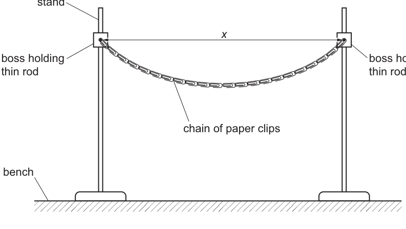
Ensure that the rods are the same height above the bench.
Slide the paper clips at the ends of the chain onto the rods.
The distance between the centres of the rods is . Position the stands so that is approximately 70 cm.
Measure and record .
= ______
Set the stands so that and measure the distance between the centres of the rods.
Example (to nearest ):
x = 70.0 cm (example)
Background Concept
In practical work, the quality of any later analysis depends strongly on how well the apparatus matches the intended geometry. Measuring a distance between centres is often harder than measuring between edges, because you must identify the centre position consistently.
Understanding the Question
You must set up the chain between two rods (same height) and measure , the distance between the centres of the rods, with about .
Approach
- Build the arrangement as shown so the chain is supported at both ends.
- Adjust the stands until the separation is near .
- Measure carefully (centre-to-centre), then record it with unit and appropriate precision.
Step-by-Step Reasoning
- Ensure the rods are at the same height above the bench so the chain is approximately symmetric and not twisted.
- Slide the end paper clips onto the rods so the chain can move/oscillate freely.
- Use a ruler/metre rule to measure the horizontal separation of the rod centres.
- If measuring edge-to-edge is easier, you can measure between the same edges of each rod and then correct to centre-to-centre by adding/subtracting one radius as appropriate.
- Record in to the precision allowed by the rule (commonly if reading to the nearest mm).
Key Takeaways
- Follow set-up instructions (especially “same height”) to reduce systematic errors.
- Identify what exactly must be measured (centre-to-centre).
Common Mistakes
- Measuring between the outer edges of rods and calling it .
- Not ensuring the rods are the same height, causing a sloping chain.
- Recording with no unit.
Things to Be Careful About
- Ensure the ruler is parallel to the bench and aligned with the rod centres (avoid diagonal measurements).
- If the rod thickness is significant, uncertainty in locating the centre can dominate the uncertainty in .
Use the hook to attach the smaller sphere of modelling clay to the chain of paper clips as shown in Fig. 2.3.
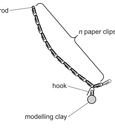
The number of paper clips between the hook and the end of the chain is , as shown in Fig. 2.3.
Place the hook so that is 11.
Calculate , where
Give your answer to three significant figures.
= ______
(to )
N = 4.95
Background Concept
Many practical questions define a derived quantity to simplify later calculations or graphs. Here
so is dimensionless because is a count.
Understanding the Question
You are told to place the hook so that paper clips lie between the hook and the end, then calculate and give it to three significant figures.
Approach
Substitute into the given expression and evaluate. Finally round to .
Step-by-Step Reasoning
- Substitute :
- Square :
- Take the cube root:
- Round to three significant figures:
Key Takeaways
- Convert roots into fractional indices: .
- Always follow the stated significant-figure requirement.
Common Mistakes
- Calculating instead of .
- Rounding too early.
- Giving with a unit (it has none).
Things to Be Careful About
- Ensure your calculator is interpreting the cube root correctly (use brackets for ).
- Three significant figures means 4.95, not 4.9 or 4.9500.
Pull the sphere towards you through a short distance. When the sphere is released, it will oscillate.
Take measurements to determine the period of these oscillations.
= ______
Time oscillations and repeat.
Example:
T = 1.19 s (example)
Background Concept
The period is the time for one complete oscillation. Measuring a single period directly with a stopwatch gives a large percentage uncertainty because reaction time (starting/stopping) is a significant fraction of . A standard improvement is to time oscillations (e.g. or ) and then divide by :
Repeating the timing and averaging reduces random uncertainty.
Understanding the Question
You must obtain the period of the oscillations of the modelling clay sphere attached to the paper-clip chain. You are expected to describe (by your method) and then record a value of .
Approach
- Displace the sphere slightly and release to start oscillations.
- Use a stopwatch to time a reasonably large number of oscillations (commonly 10 or more).
- Repeat the measurement and take a mean.
- Divide by the number of oscillations to obtain .
Step-by-Step Reasoning
- Pull the sphere a small distance and release so it oscillates with small amplitude (more repeatable period).
- Choose a reference point (e.g. when the sphere passes the centre position moving towards you).
- Start timing as the sphere passes the reference point, count complete oscillations, and stop timing when it again passes the reference point in the same direction.
- Repeat at least once more.
- Average the measured total times and divide by to get .
Example:
Key Takeaways
- Timing multiple oscillations reduces the effect of reaction time.
- Repeats and a mean improve reliability.
Common Mistakes
- Timing only one oscillation (very large percentage uncertainty).
- Not defining a consistent start/stop point (e.g. starting at centre but stopping at an end).
- Counting half-oscillations instead of full oscillations.
Things to Be Careful About
- Damping may cause amplitude to decrease; try to time early oscillations consistently.
- Large amplitudes can change the period slightly; keep the initial displacement small.
- Ensure the chain is oscillating in one plane and not twisting, otherwise the motion becomes irregular.
Roll the two spheres into one larger sphere.
Measure and record the diameter of the larger sphere.
= ______
Repeat (b) and (c) with a value of approximately 80 cm and with the hook placed so that is 7.
= ______
= ______
= ______
Example measurements (student-dependent):
Larger sphere diameter:
With :
With :
(to )
Period by timing oscillations and averaging, e.g.
Example: d = 3.00 cm, x = 80.0 cm, N = 3.66, T = 1.01 s
Background Concept
This part extends the experiment by changing the mass (by combining the clay spheres) and changing the geometry ( and ). Good practical work means keeping the measurement method consistent between the two runs so that comparisons (and later calculation of ) are meaningful.
Understanding the Question
You must:
- make a larger sphere (combining the two smaller spheres), then measure its diameter ;
- repeat the set-up with ;
- place the hook so and calculate ;
- measure the new period using the same timing method as in (c).
Approach
Follow the same sequence each time:
- Measure carefully.
- Adjust stands to achieve the required and measure it.
- Set by counting clips; compute .
- Time multiple oscillations, repeat, average, and calculate .
Step-by-Step Reasoning
- Diameter of the larger sphere: measure with ruler, record with unit and suitable precision.
- Rod separation : measure centre-to-centre as before (consistency matters).
- Compute for :
- Period : time (e.g.) oscillations at least twice and average:
Key Takeaways
- Consistency between runs reduces systematic differences.
- Derived quantities should be calculated to the requested significant figures.
Common Mistakes
- Forgetting to change to approximately .
- Miscounting (counting links incorrectly).
- Timing method changes between runs, making values not comparable.
Things to Be Careful About
- When rolling the larger sphere, it may not be perfectly spherical; measure the widest diameter without squashing it.
- Keep the oscillation amplitude small in both runs so that any comparison is fair.
- Record and with sensible precision (not more precise than the instrument).
It is suggested that the relationship between , , and is
where is a constant.
Using your data, calculate two values of .
first value of = ______
second value of = ______
From
Example (convert to ):
First set: , , ,
Second set: , , ,
Example: k1 = 5.8 s^2 m, k2 = 5.9 s^2 m
Background Concept
When an experiment proposes a relationship with an unknown constant , you test it by rearranging the equation to calculate from each set of measurements. If the relationship is correct and the uncertainties are reasonable, the calculated values of should agree within experimental uncertainty.
Given
rearrange to
Consistency of units is essential (typically SI: and in metres).
Understanding the Question
You have two runs of the experiment (small sphere with , and larger sphere with ). Using your measured values of , , and for each run, you must calculate two values of .
Approach
For each run:
- Convert lengths to consistent units.
- Substitute into .
- Compute and record it with appropriate significant figures (addressed in part (ii)).
Step-by-Step Reasoning
- Start from the given model and rearrange to make the subject.
- Use the measured and square it.
- Convert and to metres (or keep all lengths in cm, but then will have different units; SI is usually preferred).
- Calculate .
- Divide by .
- Repeat for the second set.
If your two values are close, it suggests the proposed relationship is reasonable.
Key Takeaways
- Rearranging to calculate a constant is a standard way to test a relationship.
- Unit consistency matters: changing cm to m changes the numerical value (and unit) of .
Common Mistakes
- Using (incorrect rearrangement).
- Forgetting to square or .
- Mixing units (e.g. in cm and in m).
Things to Be Careful About
- is dimensionless; only , , and carry units.
- Because the experiment is relatively uncertain, quoting an over-precise is not justified (handled explicitly in part (ii)).
Since the uncertainty in is of order , should be quoted to about .
(For example, and .)
Quote k to 2 s.f. (uncertainty ≈ 15%)
Background Concept
Significant figures should reflect the precision of the data. A useful rule is: if a quantity has a percentage uncertainty of about to , quoting more than is usually unjustified because the third significant figure is not meaningful.
Understanding the Question
You must explain why you gave your particular number of significant figures for . This requires linking your reported precision to the uncertainties in your measurements (and/or the stated overall uncertainty in ).
Approach
Use the dominant uncertainty argument:
- either refer to the stated uncertainty in ,
- or refer to the least precisely measured quantities (often timing and the centre-to-centre measurement of ).
Then state that (or at most if your uncertainties are smaller) is appropriate.
Step-by-Step Reasoning
- A uncertainty means the true value could plausibly differ by roughly .
- For , that is about .
- Quoting as would suggest uncertainty of order , which is far smaller than the experimental uncertainty.
- Therefore, should be quoted to about (e.g. or ).
Key Takeaways
- Significant figures must be consistent with experimental uncertainty.
- Larger uncertainties justify fewer significant figures.
Common Mistakes
- Quoting many digits from a calculator without justification.
- Justifying sig figs only by “what the calculator shows”.
Things to Be Careful About
- If you used different units (cm vs m), your numerical value of changes, but the reasoning about significant figures does not: it still depends on the relative (percentage) uncertainty.
It is suggested that the percentage uncertainty in the values of is 15%.
Using this uncertainty, explain whether your results support the relationship in (e).
Using uncertainty, compare the two values.
Example:
With and :
So the results support the relationship.
Yes — k values agree within 15%, so relationship is supported.
Background Concept
To decide whether results support a proposed relationship, you compare outcomes from different runs. If the model is correct, the calculated constant should be consistent. With an estimated percentage uncertainty (here ), you check whether the difference between values is small enough to be explained by that uncertainty.
A common comparison is percentage difference:
Understanding the Question
You are told the percentage uncertainty in is . You must use this to judge whether your two calculated values of are consistent, and therefore whether your data supports the suggested relationship.
Approach
- Compute the percentage difference between and .
- If the percentage difference is less than (or comparable to) , conclude the results support the relationship; otherwise they do not.
Step-by-Step Reasoning
- Calculate the absolute difference .
- Divide by the mean value .
- Convert to a percentage.
- Compare to .
If, for example, the difference is only a few percent, it is well within , so the two values are consistent.
Key Takeaways
- A relationship is supported when repeated/alternative runs give a consistent constant within uncertainty.
- Always use the stated uncertainty to justify your conclusion.
Common Mistakes
- Saying “they are close” without quantifying.
- Comparing using absolute difference only (without considering the scale of ).
Things to Be Careful About
- If your values differ by slightly more than , a cautious conclusion is that results do not clearly support (or are inconclusive) given the uncertainty estimate.
- Ensure you use the same units for both values before comparing.
Describe four sources of uncertainty or limitations of the procedure for this experiment.
For any uncertainties in measurement that you describe, you should state the quantity being measured and a reason for the uncertainty.
- Uncertainty in : reaction time when starting/stopping the stopwatch and judging the reference point as the sphere passes.
- Uncertainty in : difficult to measure centre-to-centre of rods; rod thickness and alignment cause reading uncertainty.
- Uncertainty in : modelling clay sphere not perfectly spherical / may deform when measured, so diameter varies with direction.
- Limitation affecting : oscillations damped and/or motion not in a single plane (twisting of chain), making the period harder to time consistently.
See working (four uncertainties/limitations listed).
Background Concept
An uncertainty is a quantified (or described) doubt in a measurement, often random (scatter between repeats) or systematic (a consistent bias). A limitation is a feature of the method that prevents ideal conditions (e.g. damping, poor control of variables). Good answers name the quantity affected and explain the physical reason.
Understanding the Question
You must give four sources of uncertainty or limitations for this experiment. For measurement uncertainties, you must state the quantity being measured and why it is uncertain.
Approach
Scan the experiment for:
- measurements: , , , and the count ;
- procedural limitations: damping, non-planar motion, inconsistent amplitude, changing support conditions.
State four distinct points, each with a clear link to the quantity and a reason.
Step-by-Step Reasoning
Examples of creditworthy points:
- Timing uncertainty in : starting/stopping a stopwatch depends on human reaction time and judgement of the exact moment the sphere passes a reference point.
- Distance uncertainty in : is centre-to-centre; rod thickness makes the centre hard to locate, and the ruler may not be perfectly aligned horizontally.
- Diameter uncertainty in : modelling clay can deform and may not be a true sphere; different measured diameters are possible depending on orientation/pressure.
- Motion limitation affecting : damping reduces amplitude and the chain may twist, so the oscillation is not perfectly simple harmonic in one plane; this reduces repeatability of timing.
Other acceptable limitations could include: rods not exactly the same height causing asymmetry; amplitude not kept small; difficulty ensuring the hook is placed consistently at the same link.
Key Takeaways
- Always state the quantity and the reason.
- Provide distinct, non-overlapping sources.
Common Mistakes
- Writing vague phrases like “human error” with no quantity or mechanism.
- Repeating the same idea (e.g. stopwatch reaction time) in different words for multiple points.
- Listing improvements instead of limitations.
Things to Be Careful About
- “Uncertainty in ” is usually weak because is a count; only creditable if you explain ambiguity in what counts as “between hook and end”.
- Avoid claiming impossible precision (e.g. timing to with a manual stopwatch).
Describe four improvements that could be made to this experiment. You may suggest the use of other apparatus or different procedures.
- Measure more accurately: use a motion sensor/video analysis/light gate (or time a larger number of oscillations) to reduce reaction-time error.
- Improve measurement of : mark rod centres and use a set square/tape measure aligned horizontally; keep stands fixed (e.g. clamp bases) to prevent movement.
- Improve measurement of : use vernier calipers and measure diameter in several orientations, then average.
- Improve the oscillations: keep amplitude small and add a fiducial marker so the same reference point is used; ensure the chain oscillates in one plane (prevent twisting).
See working (four improvements listed).
Background Concept
Improvements should directly address identified uncertainties/limitations by either:
- reducing random uncertainty (e.g. better timing method, more repeats),
- reducing systematic errors (e.g. better alignment and definitions of what is measured),
- improving control of variables (e.g. consistent amplitude, preventing twisting).
Understanding the Question
You must describe four improvements. They can involve better apparatus or better procedure. Each must be realistic in a school/college lab and clearly linked to how it improves the data quality.
Approach
Take the main problem areas (, , , and the nature of the oscillation) and propose one strong improvement for each. Ensure you give four distinct ideas.
Step-by-Step Reasoning
Examples:
- Reduce timing uncertainty in : use video analysis (frame-by-frame) or a motion sensor/data logger to obtain period without manual reaction time; alternatively, time oscillations and repeat several times.
- Improve measurement: define the rod centre positions (e.g. mark them), measure with a tape measure kept horizontal using a set square, and secure stand bases so they do not slip during measurements.
- Improve measurement: use vernier calipers and measure in several directions to account for non-sphericity; average to reduce random variation.
- Improve oscillation quality: keep displacement small, use a clear fiducial marker and a fixed reference line, and prevent twisting so motion stays in one plane (more repeatable period).
Key Takeaways
- Good improvements are specific and linked to a particular limitation.
- Better instruments and more repeats typically reduce uncertainty.
Common Mistakes
- Suggesting vague improvements like “be more careful”.
- Repeating the same improvement idea (e.g. “repeat more” in multiple ways).
- Suggesting unrealistic equipment without explaining how it would be used.
Things to Be Careful About
- Improvements should not change the intended physics model (e.g. making large amplitudes to make timing easier can change the period).
- If you propose new apparatus (e.g. motion sensor), state what it measures and how you would extract from the recorded data.