Physics 9702/22 — October/November 2024
Cambridge AS Level · AS Level Structured Questions · worked solutions for every part, with the mark scheme
Topics Dynamics · Work, Energy and Power · Physical Quantities and Units · Forces, Density and Pressure · Kinematics · Deformation of Solids · +5 more
Answer
A vector quantity is one that has both magnitude and direction.
A vector quantity has both magnitude and direction.
Background Concept
Physical quantities are either scalars or vectors.
- A scalar is described completely by its magnitude (a single number with a unit), e.g. mass, time, temperature.
- A vector needs both magnitude and direction to describe it fully, e.g. displacement, velocity, force.
Understanding the Question
You are asked to state what is meant by a vector quantity. This is a definition question, so a short, precise statement is enough.
Approach
Give the standard definition: include the two essential features.
Step-by-Step Reasoning
A quantity is a vector if:
- It has a size (magnitude), and
- It has a specified direction.
So the definition is “a quantity with magnitude and direction”.
Key Takeaways
- Vectors: magnitude + direction.
- Scalars: magnitude only.
Common Mistakes
- Saying “a quantity with direction” but not stating magnitude.
- Giving examples only, without stating the definition.
Things to Be Careful About
- The wording must explicitly include direction; “has a sign” is not the same as “has a direction”.
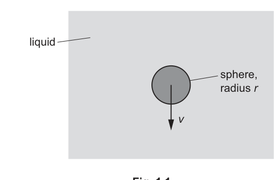
A sphere falls vertically through a liquid that has density . The sphere has radius and constant velocity , as shown in Fig. 1.1.
The drag force acting on the sphere is given by
where is a property of the liquid.
Determine the SI base units of .
SI base units = ______
Working
From
Units:
Answer
SI base units of :
kg m^-1 s^-1
Background Concept
If an equation is physically correct, it must be dimensionally consistent (homogeneous): both sides have the same units.
Here,
The factor is a pure number (dimensionless), so it does not affect units. The units must therefore satisfy
Understanding the Question
You are given a formula for the drag force on a sphere moving through a liquid. You must find the SI base units of (the liquid property, viscosity).
Known SI units:
- force in newtons (N)
- radius in metres (m)
- speed in metres per second ()
Approach
- Rearrange the equation to make the subject.
- Replace each quantity with its SI units (in base form).
- Simplify to get the base units of .
Step-by-Step Reasoning
Start with
Rearrange:
Now insert units.
So
Combine the denominator: .
Then
Key Takeaways
- Use dimensional analysis: .
- Remember .
- Numerical constants like do not affect units.
Common Mistakes
- Leaving the unit as without converting to base units (the question asks for SI base units).
- Treating as having units.
- Forgetting that has in its unit.
Things to Be Careful About
- Always reduce force to .
- Track powers of metres carefully: you divide by and by , so you divide by and by .
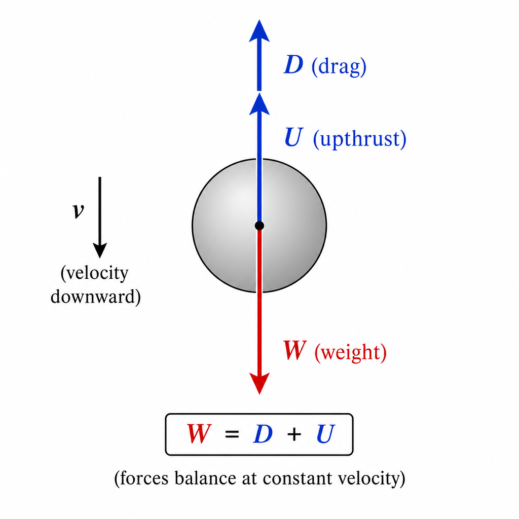
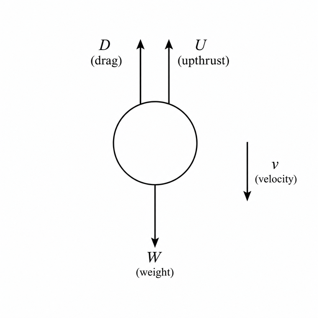
State an equation showing the relationship between the magnitudes of the weight , drag force and upthrust acting on the sphere.
Answer
Constant velocity resultant force , so
W = D + U
Background Concept
Newton's first law (or with ) tells us:
- If an object moves with constant velocity, its acceleration is zero, so the resultant force is zero.
For a falling object in a fluid, the typical vertical forces are:
- weight acting downward
- drag force acting upward (opposes motion)
- upthrust acting upward
Understanding the Question
The sphere falls at constant velocity through the liquid. The question asks for an equation relating the magnitudes of , , and .
Approach
Use force balance in the vertical direction: downward force(s) = upward force(s).
Step-by-Step Reasoning
Because the velocity is constant,
Downward force is .
Upward forces are and .
So the balance is
Key Takeaways
- Constant velocity means .
- Therefore the forces are in equilibrium: total up = total down.
Common Mistakes
- Writing (wrong sign: both and act upward).
- Writing without clarifying directions or that these are magnitudes.
Things to Be Careful About
- The question asks for magnitudes, so the standard mark-scheme form is .
- Drag always opposes the motion: since the sphere moves downward, drag is upward.
The volume of the sphere is . The drag force is .
Calculate the weight of the sphere.
weight = ______
Working
Volume:
Upthrust:
Constant velocity :
Answer
0.36 N
Background Concept
The upthrust on an object in a fluid is equal to the weight of fluid displaced (Archimedes' principle):
where is the fluid density, is gravitational field strength, and is the volume displaced.
If the object is moving at constant velocity, then and the forces balance:
Understanding the Question
You are given:
- liquid density
- sphere volume
- drag force
- the sphere falls at constant velocity
You must calculate the weight of the sphere.
Approach
- Convert the volume to so it matches the SI density unit.
- Use to find the upthrust.
- Use force balance to get the weight.
Step-by-Step Reasoning
1) Convert volume
Since ,
So
2) Calculate upthrust
Compute:
This is much smaller than the weight because the volume is only a few cubic centimetres.
3) Use equilibrium to find weight
At constant velocity, resultant force is zero, so
To 2 s.f.,
Key Takeaways
- Always convert to consistent SI units before using formulas.
- Upthrust is .
- Constant velocity implies force balance: .
Common Mistakes
- Using (wrong: that would be litres, not ).
- Forgetting to add upthrust, and taking .
- Using (missing ).
Things to Be Careful About
- Check the power of ten in the conversion: gives .
- Use an appropriate value of (usually or ).
- Give the final weight with a sensible number of significant figures consistent with the data.
Answer
Momentum is the product of mass and velocity:
Momentum is the product of mass and velocity: p = mv.
Background Concept
Linear momentum is a measure of “quantity of motion”. For a body of mass moving with velocity , momentum is defined by
Momentum is a vector, so it has the same direction as the velocity.
Understanding the Question
You are asked to give the definition of momentum. No calculation is needed.
Approach
State the standard definition using symbols and (optionally) mention that it is a vector.
Step-by-Step Reasoning
- Identify the relevant definition: momentum depends on mass and velocity.
- Write the definition in equation form: .
Key Takeaways
- Momentum is defined as mass multiplied by velocity.
- Momentum is a vector quantity.
Common Mistakes
- Writing (confusing with kinetic energy).
- Omitting that momentum is a vector when the question context involves direction.
Things to Be Careful About
- Use velocity (a vector), not speed (a scalar), if the definition is requested precisely.
A child stands on a scooter on horizontal ground. The combined mass of the child and the scooter is .
The child starts from rest and pushes once on the ground with her foot which causes her to accelerate. The push lasts for a time of . The speed of the child and the scooter after the push is .
Determine the average resultant force acting horizontally on the child and the scooter during the push.
average force = ______
Working
Change in momentum:
Average resultant force:
Answer
8.7 N
Background Concept
A resultant force causes a change in momentum. The average resultant force over a time interval is
This comes from , and the product is the impulse.
Understanding the Question
- Total mass (child + scooter): .
- Starts from rest: .
- Final speed after push: .
- Duration of push: .
You must find the average horizontal resultant force during the push.
Approach
- Calculate change in momentum .
- Divide by the time for which the push acts: .
Step-by-Step Reasoning
- Initial momentum is zero because the system starts from rest.
- Final momentum is .
- So the change in momentum is
- Average resultant force is
Key Takeaways
- Impulse: .
- For a given mass, larger or smaller means a larger average force.
Common Mistakes
- Using without first finding (which is fine, but more steps and easy to slip).
- Forgetting to use the combined mass of child and scooter.
- Not dividing by the time interval.
Things to Be Careful About
- The force asked for is the average resultant force horizontally, not the force from the foot alone.
- Quote the answer with sensible significant figures based on the data (here, 2 s.f.).
Later, the child in (b) travels down a slope at a constant angle to the horizontal, as shown in Fig. 2.1.
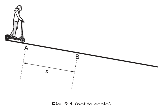
At point A her speed is . She has a constant acceleration of parallel to the slope. After a time of , she reaches point B.
Calculate the distance travelled by the child along the slope from A to B.
= ______
Working
With , , ,
Answer
8.0 m
Background Concept
For motion with constant acceleration along a straight line, the displacement after time is related to initial velocity by the SUVAT equation
This applies when the acceleration is constant and the motion is along one direction (here: parallel to the slope).
Understanding the Question
From point A to point B (along the slope):
- initial speed at A:
- acceleration (constant, along slope):
- time taken:
We want the distance travelled along the slope in this time.
Approach
Use a constant-acceleration equation that links , , , and . The most direct is .
Step-by-Step Reasoning
- Write the equation:
- Substitute values:
- Evaluate:
So
Key Takeaways
- Choose the SUVAT equation that contains only known quantities and the unknown.
- “Parallel to the slope” means treat the motion as 1D along the slope.
Common Mistakes
- Using without knowing .
- Forgetting the in .
- Rounding too early (can shift the final value).
Things to Be Careful About
- Ensure units are consistent: , , give .
- Quote the final answer to an appropriate number of significant figures (here, 2 s.f. matches the given data).
At point B, the child in (c) applies the brake with a constant force to maintain a constant velocity. Point C is from point B, as shown in Fig. 2.2.
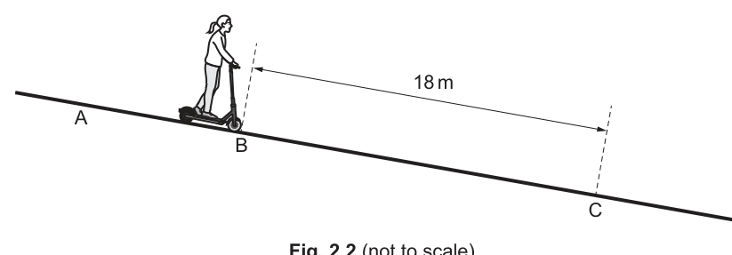
The work done by the braking force between B and C is .
Working
Work done by a constant braking force:
Answer
14 N
Background Concept
Work done by a force is the energy transferred when the force causes a displacement. For a constant force acting parallel (or antiparallel) to the displacement,
If the force is opposite the motion (a braking force), the work done by that force on the object is negative. However, questions often give the magnitude of the work done (energy dissipated), which is a positive number.
Understanding the Question
Between B and C:
- distance along the slope:
- braking is applied with a constant force to maintain constant velocity
- magnitude of work done by braking force:
We need the magnitude of the braking force.
Approach
Use with magnitudes: .
Step-by-Step Reasoning
- Start with
- Rearrange:
- Substitute:
Key Takeaways
- For constant force parallel to displacement, work is force times distance.
- Braking removes energy; the given work is typically the energy dissipated (a magnitude).
Common Mistakes
- Using instead of .
- Forgetting that is the distance along the slope between B and C.
- Treating as negative in the calculation when the question asks for magnitude.
Things to Be Careful About
- If direction/sign were required: the braking force is opposite to the motion along the slope.
- Significant figures: (2 s.f.) and (2 s.f.) justify an answer of (2 s.f.).
On Fig. 2.3, sketch the variation of the kinetic energy of the child and scooter with distance travelled from point A to point C.
Numerical values for kinetic energy are not required.
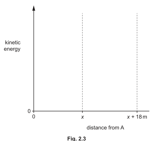
Answer
From A to B (distance to ): kinetic energy increases linearly with distance (straight line with positive gradient), starting at a non-zero value at A.
From B to C (distance to ): kinetic energy is constant (horizontal line).
KE increases linearly from A to B, then remains constant from B to C.
Background Concept
Kinetic energy is
The work-energy principle states that the net work done on an object equals the change in its kinetic energy:
If the resultant force along the direction of motion is constant, then the work done by this resultant force over distance is , so
That means kinetic energy varies linearly with distance when the resultant force is constant.
Understanding the Question
You must sketch kinetic energy (vertical axis) against distance from A (horizontal axis), from A to C.
- From A to B: the child accelerates at constant , so her speed (and hence ) increases.
- From B to C: brakes are applied so that velocity is constant, so speed (and hence ) does not change.
The graph has two regions, separated at distance .
Approach
- Decide the trend of in each region using speed/acceleration information.
- Decide the shape (curved or straight) using the work-energy principle:
- constant acceleration implies constant resultant force (since ), so increases linearly with distance.
- constant velocity implies , so the graph is horizontal.
Step-by-Step Reasoning
From A to B (distance to ):
- Initial speed at A is , so at distance is not zero. The curve must start above the origin.
- Acceleration is constant, so resultant force along slope is constant:
- Net work done over distance is , so
Therefore, increases as a straight line with distance from A up to .
From B to C (distance to ):
- Braking produces constant velocity, so acceleration is zero and kinetic energy is constant.
- Hence the graph is a horizontal line from to .
So the sketch should show a straight rising line up to the dashed line at , then a flat line to the dashed line at .
Key Takeaways
- Constant acceleration constant resultant force increases linearly with distance.
- Constant velocity constant.
- Non-zero initial speed means the graph does not start at zero kinetic energy.
Common Mistakes
- Starting the kinetic energy at zero at A (even though ).
- Drawing a curved increase between A and B (it is linear with distance if the resultant force is constant).
- Drawing a decreasing kinetic energy from B to C: the brakes do negative work, but gravitational potential energy is also decreasing; constant velocity means these effects balance so stays constant.
Things to Be Careful About
- The horizontal axis is distance from A, so the “kink” in the graph must occur exactly at , not at .
- No numerical values are required, but the shape and piecewise behaviour must be correct (increase then constant).
The variation of stress with strain for a metal P is shown in Fig. 3.1.
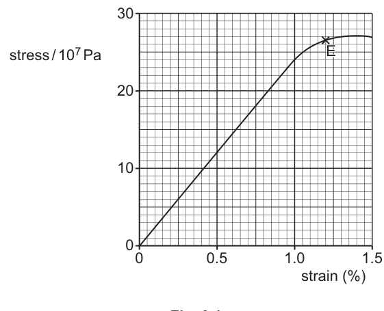
Point E is the elastic limit of the metal.
Working
Young modulus is the gradient of the straight-line part:
Take a point on the straight-line section, e.g. at strain ,
stress .
Answer
2.5 × 10^10 Pa
Background Concept
Young modulus measures stiffness:
- Stress (unit: Pa).
- Strain (no unit).
- This definition applies in the linear (proportional) region of the stress–strain graph (Hooke’s law region), where stress is directly proportional to strain.
On a stress–strain graph, the Young modulus is the gradient of the straight-line part.
Understanding the Question
Fig. 3.1 gives stress (vertical axis) against strain in % (horizontal axis). You must use the straight portion near the origin and determine its gradient.
Key point: the x-axis is in percent, so you must convert e.g. to before dividing.
Approach
- Choose a convenient point on the straight-line region (not on the curved part).
- Read off stress and strain.
- Convert strain from % to a decimal.
- Calculate .
Step-by-Step Reasoning
- From the graph, at about strain , stress is about on the scale of .
Convert values:
- Stress: .
- Strain: .
Now divide:
(Any similar choice of point on the straight line gives a similar value.)
Key Takeaways
- Young modulus is the gradient of the straight-line (Hooke’s law) part of a stress–strain graph.
- Always convert % strain to a decimal before using .
Common Mistakes
- Using strain as “1.0” instead of “0.010” (gives error).
- Using point E (elastic limit) even though the graph is no longer linear there.
- Forgetting the factor on the stress axis.
Things to Be Careful About
- Pick a point clearly on the straight-line section.
- Quote in Pa and to a sensible number of significant figures (typically 2–3, matching graph reading precision).
On the line in Fig. 3.1, draw a cross () to show the limit of proportionality. Label this point Q.
Answer
Place at the end of the initial straight-line section (where the graph first begins to curve away from a straight line).
Q at the end of the straight-line (proportional) region.
Background Concept
The limit of proportionality is the greatest stress for which stress is directly proportional to strain (Hooke’s law region). On a stress–strain graph, it is the point where the graph first departs from a straight line through the origin.
This is not necessarily the same as the elastic limit (point E), which is the greatest stress for which the material returns to its original length when unloaded.
Understanding the Question
You are asked to mark point on Fig. 3.1. The graph is straight from the origin and then begins to curve; should be placed at the transition between these behaviours.
Approach
- Follow the straight-line region starting from the origin.
- Find the first noticeable deviation from that straight-line trend.
- Mark that point with a cross and label it .
Step-by-Step Reasoning
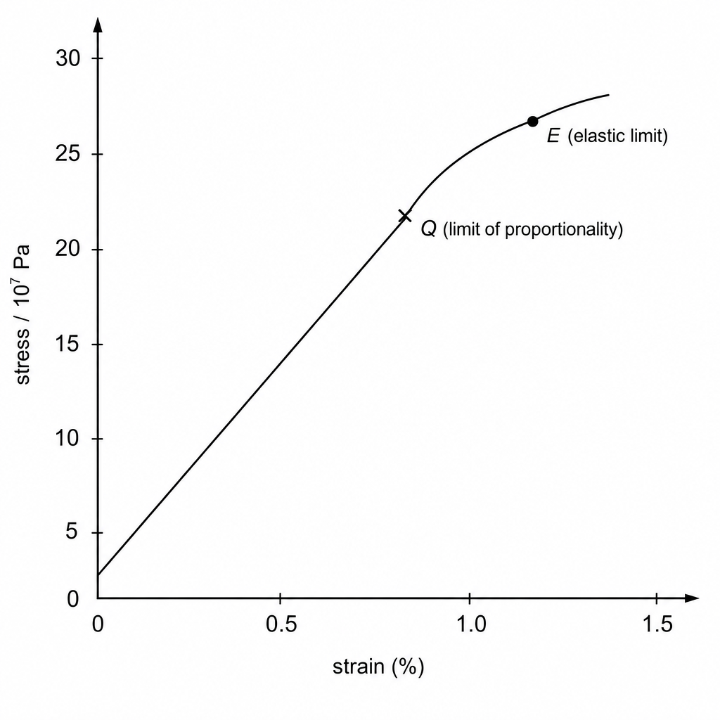
- The proportional region is the straight line from the origin.
- As strain increases, the plotted line starts to bend (curvature develops).
- The point at which curvature begins is the limit of proportionality, so that is where is placed.
Key Takeaways
- “Proportional” means a straight line through the origin.
- The limit of proportionality is where straight-line behaviour ends, not where elastic behaviour ends.
Common Mistakes
- Placing at point E (elastic limit) instead of earlier.
- Placing somewhere on the curved region without identifying the start of curvature.
Things to Be Careful About
- The limit of proportionality is usually slightly before the elastic limit for metals.
- Choose the point where the deviation first becomes clear (not a point far along the curve).
Answer
Resultant force on the object is zero.
Resultant moment (torque) about any point is zero (clockwise moments = anticlockwise moments).
Net force = 0 and net moment about any point = 0.
Background Concept
An object in equilibrium is not accelerating (translationally or rotationally).
So there are two independent conditions:
- Translational equilibrium:
- Rotational equilibrium:
where is the moment (torque) of a force about a chosen point, .
Understanding the Question
The question asks you to state the conditions (not calculate anything). For 2 marks, you must give both conditions: no net force and no net turning effect.
Approach
Write one statement about forces, and one statement about moments/torques.
Step-by-Step Reasoning
- If the resultant force were not zero, Newton’s second law would give a non-zero acceleration, so the object would not be in equilibrium.
- If the resultant moment were not zero, there would be an angular acceleration, so the object would start rotating.
Thus both must be zero.
Key Takeaways
- Equilibrium requires both and .
- “Clockwise moments = anticlockwise moments” is an acceptable way to express .
Common Mistakes
- Stating only and forgetting moments.
- Saying “forces are equal” without specifying resultant is zero (forces could be equal but not opposite).
Things to Be Careful About
- The moment condition is true about any point; choosing a convenient point is used in calculations, but the condition itself must always hold for equilibrium.
A wire is used to hold a uniform shelf AB horizontally in equilibrium as shown in Fig. 3.2.
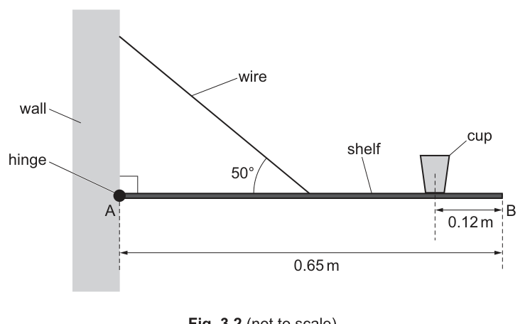
The wire is connected to the midpoint of shelf AB at an angle of to the horizontal. The shelf is attached to a wall by a hinge at A. The length of shelf AB is and its weight is .
A cup of weight rests on the shelf with its centre of gravity at a horizontal distance of from B.
Working
Take moments about hinge at .
Distances from :
- midpoint:
- cup:
Only the vertical component of tension produces a moment:
Answer
46 N
Background Concept
For a rigid body in equilibrium, the total clockwise moment about any point equals the total anticlockwise moment about that point.
Moment magnitude is:
where is the perpendicular distance from the pivot to the line of action of the force.
Choosing the hinge point as the pivot is useful because hinge forces then have zero moment (their line of action passes through the pivot).
Understanding the Question
A horizontal uniform shelf of length is hinged at . A wire is attached at the shelf’s midpoint, making to the horizontal. The shelf weight is acting at its midpoint. A cup of weight acts at a point from (so from ). You must find the wire tension using moments about .
Approach
- Draw/visualise forces and their distances from .
- Take moments about to remove the unknown hinge reaction.
- Use only the component of tension perpendicular to the shelf (vertical component) because the horizontal component passes through along the shelf and gives no turning effect about .
- Solve for .
Step-by-Step Reasoning
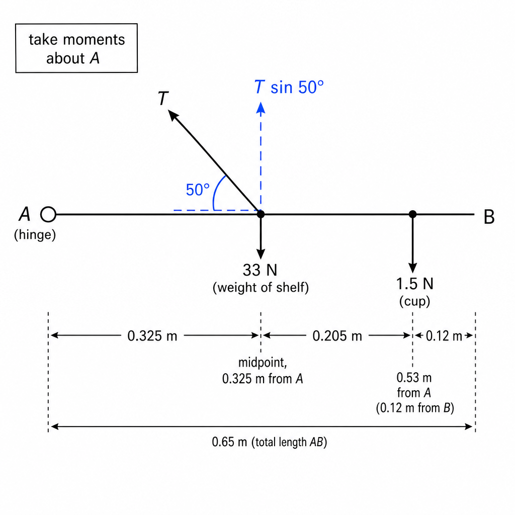
Distances:
- Midpoint from is .
- Cup position from is .
Moments about :
- Shelf weight produces clockwise moment: .
- Cup weight produces clockwise moment: .
- Tension produces anticlockwise moment through its vertical component at distance :
Compute RHS:
- Total
So:
Then:
Key Takeaways
- Take moments about a point that removes unknown forces (here, the hinge).
- Use perpendicular components for moments: only contributes.
Common Mistakes
- Using instead of .
- Using the wrong cup distance (using from instead of from ).
- Forgetting that the shelf’s weight acts at its midpoint.
Things to Be Careful About
- Be consistent with clockwise vs anticlockwise signs.
- Use distances measured from the pivot point .
- Keep units as N and m so moments are in N m.
Working
Answer
9.9 × 10^-4 m
Background Concept
Stress is defined as force per unit cross-sectional area:
For a cylindrical wire of radius :
So:
Understanding the Question
You are told the stress in the wire is and you have found the wire tension from part (i). You must use to find the wire radius.
Approach
- Use .
- Rearrange to get .
- Substitute values and compute.
Step-by-Step Reasoning
Start from:
Rearrange:
Substitute and :
This is about , which is a reasonable wire radius.
Key Takeaways
- Stress uses the axial force in the wire: here it is the tension .
- For a circular cross-section, use and take a square root to get .
Common Mistakes
- Using diameter instead of radius in .
- Forgetting to use .
- Using instead of for stress (stress depends on the force along the wire, i.e. the tension itself).
Things to Be Careful About
- Units: , so comes out in and in m.
- Significant figures should match the input (typically 2–3 s.f.).
More items are added to the shelf, doubling the stress in the wire. The wire is made of the metal P from (a).
Use Fig. 3.1 to state and explain whether the wire will behave plastically or elastically as the stress doubles.
Answer
Doubling the stress gives .
From Fig. 3.1 the elastic limit is at about , so is well below the elastic limit.
Therefore the wire behaves elastically (no permanent extension).
Elastically (stress still below elastic limit).
Background Concept
- Elastic behaviour: when the load is removed, the material returns to its original length (no permanent deformation).
- Plastic behaviour: when the load is removed, there is permanent extension.
The elastic limit is the maximum stress for which deformation is still fully elastic.
A stress–strain graph shows where the elastic limit occurs; beyond it, unloading would not return to the original zero strain.
Understanding the Question
The wire initially has stress . More items are added so stress doubles to . The wire is made of metal P, whose elastic limit is given by point E on Fig. 3.1 (about ).
You must decide if doubling the stress takes the wire beyond the elastic limit.
Approach
- Calculate the doubled stress.
- Read the elastic limit stress from the graph.
- Compare: if applied stress < elastic limit, behaviour is elastic; if > elastic limit, plastic deformation occurs.
Step-by-Step Reasoning
- Doubled stress:
- From Fig. 3.1, point E is around:
Comparison:
So the applied stress is far below the elastic limit; the wire will extend under load but return to its original length when the load is removed (elastic behaviour).
Key Takeaways
- Plastic deformation starts only when the stress exceeds the elastic limit.
- Always compare stresses using consistent powers of ten.
Common Mistakes
- Misreading the stress axis scale () and comparing the wrong numbers.
- Confusing limit of proportionality with elastic limit.
- Concluding “plastic” simply because the stress increased.
Things to Be Careful About
- Convert graph values properly: on the axis means .
- The question asks “state and explain”: you need both the conclusion (elastic/plastic) and the comparison to the elastic limit.
With reference to the direction of transfer of energy, compare the oscillations of transverse and longitudinal progressive waves.
Answer
Energy is transferred in the direction the wave travels.
For a transverse wave, the oscillations are perpendicular to the direction of energy transfer.
For a longitudinal wave, the oscillations are parallel to the direction of energy transfer.
Transverse: oscillations ⟂ to energy transfer; Longitudinal: oscillations ∥ to energy transfer.
Background Concept
A progressive wave transfers energy from one place to another. The direction of energy transfer is the same as the direction of wave propagation.
- Transverse wave: particles of the medium oscillate at right angles to the direction the wave travels.
- Longitudinal wave: particles oscillate back-and-forth along the same line as the wave travels.
Understanding the Question
You are asked to compare transverse and longitudinal progressive waves, specifically referring to how the particle oscillations are oriented relative to the direction of energy transfer.
So you must mention:
- direction of energy transfer (along propagation), and
- whether oscillations are perpendicular or parallel to that.
Approach
State that energy transfer is along the direction of wave travel. Then give the relative direction of oscillation for each wave type.
Step-by-Step Reasoning
- In any progressive wave, the disturbance moves through the medium, carrying energy in the direction the wave propagates.
- For a transverse wave, the displacement of the medium is at right angles to that propagation direction, so oscillations are perpendicular to energy transfer.
- For a longitudinal wave, compressions/rarefactions mean the medium oscillates back and forth along the same line as propagation, so oscillations are parallel to energy transfer.
Key Takeaways
- Energy transfer direction = wave propagation direction.
- Transverse: oscillation (\perp) propagation.
- Longitudinal: oscillation (\parallel) propagation.
Common Mistakes
- Saying “energy is transferred perpendicular in a transverse wave” (false: energy transfer is still along propagation).
- Only stating “transverse is up-down, longitudinal is left-right” without referencing energy transfer/wave direction.
Things to Be Careful About
- Always compare directions relative to the same reference: the wave/energy-transfer direction.
- Use the words perpendicular and parallel (or “at right angles” and “along the same direction”) clearly.
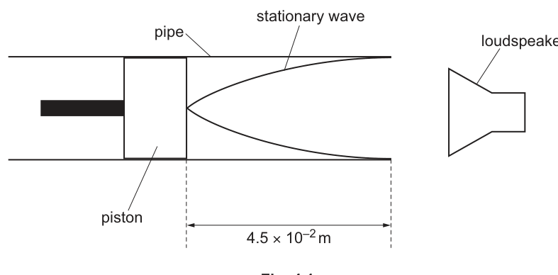
A pipe is open at one end and closed at the other with a piston. The piston can slide freely and is at a distance of from the open end of the pipe.
A loudspeaker is positioned near the open end of the pipe and emits a sound wave of a single constant frequency. A stationary wave is formed in the pipe, as illustrated in Fig. 4.1.
Answer
Place A at the open end of the pipe (displacement antinode).
A at the open end of the pipe.
Background Concept
In a stationary wave:
- A node is a point of zero displacement.
- An antinode is a point of maximum displacement.
For sound in an air column:
- At a closed end (piston), air cannot move, so there is a displacement node.
- At an open end, air can move freely, so there is a displacement antinode.
Understanding the Question
The diagram shows a pipe that is open at the loudspeaker end and closed by a piston at the other end. You are asked to mark the position of an antinode on the figure.
Approach
Use boundary conditions: open end is an antinode, closed end is a node.
Step-by-Step Reasoning
- The piston is the closed end, so it must be a displacement node.
- The open end must be a displacement antinode.
- Therefore the antinode position to label is at the open end of the pipe.
Key Takeaways
- Open end (\rightarrow) displacement antinode.
- Closed end (\rightarrow) displacement node.
Common Mistakes
- Marking an antinode at the piston end (incorrect for displacement).
- Confusing pressure nodes/antinodes with displacement nodes/antinodes.
Things to Be Careful About
- The question’s diagram (and typical A-level convention) uses the displacement pattern for the standing wave in the air column.
- For sound, pressure and displacement patterns are reversed at ends; only use displacement here unless stated otherwise.
The speed of sound in air is .
Determine the frequency of the sound wave.
frequency = ______
Working
For an open–closed pipe (node at closed end, antinode at open end),
So
Using :
Answer
1.9 × 10^3 Hz
Background Concept
A stationary wave forms when two waves of the same frequency travel in opposite directions and superpose.
For a pipe:
- Closed end: displacement must be zero (\rightarrow) displacement node.
- Open end: displacement is maximum (\rightarrow) displacement antinode.
The simplest standing-wave pattern in an open–closed pipe is a quarter of a wavelength:
Once (\lambda) is known, use the wave equation:
where (v) is wave speed, (f) frequency, (\lambda) wavelength.
Understanding the Question
The piston (closed end) is (4.5 \times 10^{-2}\ \text{m}) from the open end, so the air-column length is
The diagram shows a node at the piston and an antinode at the open end, i.e. the fundamental open–closed mode (one antinode).
You are given (v = 340\ \text{m s}^{-1}) and must find (f).
Approach
- Use the boundary conditions (node at piston, antinode at open end) to relate (L) to (\lambda).
- Substitute (\lambda) into (v=f\lambda) to get (f).
Step-by-Step Reasoning
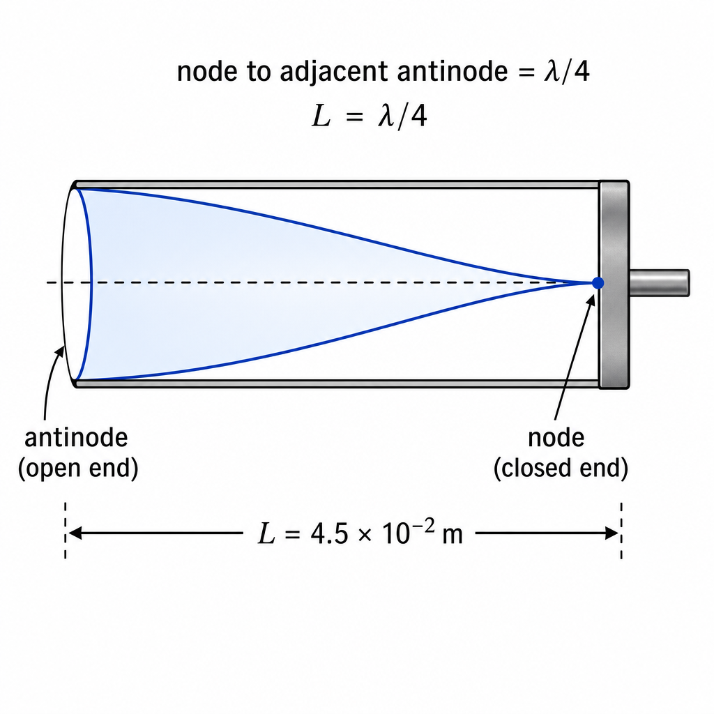
- For the mode shown, the distance from a node to the adjacent antinode is (\lambda/4). Here that distance is exactly the pipe length (L).
So
- Substitute (L = 4.5\times 10^{-2}\ \text{m}):
- Apply (v=f\lambda):
- Round appropriately (given (L) is 2 s.f.):
Key Takeaways
- Open–closed pipe fundamental mode: (L=\lambda/4).
- Convert geometry (\rightarrow) wavelength, then use (v=f\lambda).
Common Mistakes
- Using (L=\lambda/2) (that applies to an open–open or closed–closed pipe, not open–closed).
- Using (f=vL) or (f=v/4L) without first stating the (L)–(\lambda) relationship.
- Rounding too aggressively or giving an answer inconsistent with significant figures.
Things to Be Careful About
- Ensure (L) is in metres (it already is).
- Recognise which harmonic is drawn: node at one end and antinode at the other indicates an odd-quarter-wavelength mode; here it is the simplest quarter-wave.
- Keep units consistent so (f) comes out in (\text{Hz}) ((\text{s}^{-1})).
The piston is moved to the left. The frequency of the sound wave emitted by the loudspeaker is then changed so that a stationary wave is formed with same number of antinodes as in Fig. 4.1.
State and explain the change that is made to the frequency of the sound wave.
Answer
When the piston moves left, the length decreases.
For the same number of antinodes (same mode),
So decreases. With constant and , the frequency increases.
Increase the frequency.
Background Concept
In an open–closed pipe, standing-wave patterns must satisfy the boundary conditions:
- closed end: displacement node
- open end: displacement antinode
Allowed modes are odd quarter-wavelengths:
If the wave speed (v) in air is (approximately) constant, then
Understanding the Question
The piston is moved left, so the air-column length (L) becomes smaller. You then adjust the loudspeaker frequency so that a stationary wave forms with the same number of antinodes as before, meaning the same mode number (n).
You must state what happens to (f) and explain it.
Approach
- Same number of antinodes (\Rightarrow) same harmonic/mode (n), so the relationship between (L) and (\lambda) stays in the same form.
- Decreasing (L) forces (\lambda) to decrease.
- With (v) constant, smaller (\lambda) means larger (f).
Step-by-Step Reasoning
- For a particular mode (n),
- Rearranging shows
so for fixed (n), (\lambda \propto L).
3. Moving the piston left decreases (L), therefore (\lambda) must decrease to keep the same pattern (same number of antinodes).
4. Since the speed of sound in air is approximately constant,
If (\lambda) decreases, (f) increases.
Key Takeaways
- Same number of antinodes (\Rightarrow) same mode number (n).
- For fixed (n), (\lambda) changes in direct proportion to (L).
- With constant (v), decreasing (\lambda) requires increasing (f).
Common Mistakes
- Saying frequency decreases because the pipe is “shorter” without using (v=f\lambda) (you must connect length (\rightarrow) wavelength (\rightarrow) frequency).
- Assuming (\lambda) stays constant when the pipe length changes (it cannot if the same mode is to fit in the tube).
Things to Be Careful About
- The phrase “same number of antinodes” is the key clue that the harmonic number does not change.
- Don’t mix up which variable is adjusted: the piston changes (L), and you must change (f) to re-establish resonance.
- State the final change clearly: frequency increases (not wavelength).
Answer
Electric potential difference is the work done (energy transferred) per unit charge between two points:
Work done (energy transferred) per unit charge between two points, V = W/Q.
Background Concept
Electric potential difference (p.d.) tells you how much energy is transferred when charge moves between two points in a circuit.
It is defined by
where:
- is the potential difference in volts (V),
- is the work done / energy transferred in joules (J),
- is the charge moved in coulombs (C).
So .
Understanding the Question
You are asked for the definition of p.d. (not an equation you later use, and not a description involving current). The key idea is “energy per coulomb”.
Approach
State the definition in words and, if helpful, include the defining equation .
Step-by-Step Reasoning
- Potential difference compares two points in a circuit.
- When a charge moves between these points, energy is transferred.
- The potential difference is the energy transferred per unit charge, i.e. divide by .
Key Takeaways
- p.d. is an energy-per-charge quantity: .
- It is always defined between two points.
Common Mistakes
- Writing “p.d. is force per unit charge” (that is electric field, ).
- Defining it as “energy per unit current” (incorrect).
- Forgetting “between two points”.
Things to Be Careful About
- Use “work done / energy transferred per unit charge”, not “power”.
- The symbol is used both for potential difference and volts; make sure the definition is clear.
A power supply, three resistors and a component X are connected in the circuit shown in Fig. 5.1.
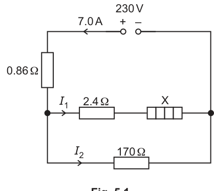
The power supply has an electromotive force (e.m.f.) of and negligible internal resistance. The current in the power supply is .
Answer
Component X is a lamp (filament lamp).
Filament lamp
Background Concept
Circuit diagrams use standard symbols so that components can be identified without extra description. A lamp (often a filament lamp) is shown by a circle with a cross inside.
Understanding the Question
The question provides a circuit diagram (Fig. 5.1) and asks you to name component X from its symbol.
Approach
Match the symbol at X to the list of standard circuit symbols you know.
Step-by-Step Reasoning
- Locate component X in the diagram.
- Identify the symbol: a lamp symbol corresponds to a filament lamp.
Key Takeaways
- Learning circuit symbols is essential: many questions begin by asking you to identify a component.
Common Mistakes
- Confusing a lamp symbol with a diode/LED symbol.
- Naming it vaguely as “a component” or “a resistor” when the symbol is specifically a lamp.
Things to Be Careful About
- The question later treats X as having a resistance (and even says its resistance does not change in part (vii)), which is consistent with modelling a filament lamp as a resistive load for circuit calculations.
Working
Current through the resistor is .
Answer
6.0 V
Background Concept
For an ohmic resistor, the potential difference across it is related to the current through it by
In a series section of a circuit, the same current flows through every component in that series section.
Understanding the Question
The resistor is in series with the rest of the network, and the supply current is given as . The question asks you to show the p.d. across that resistor is .
Approach
Use for that resistor, taking because it is in series with the supply.
Step-by-Step Reasoning
- The series resistor must carry the total supply current: .
- Substitute into Ohm’s law:
- Round to a sensible number of significant figures (here ).
Key Takeaways
- Series component (\Rightarrow) current is the supply current.
- Ohm’s law gives the p.d. directly for a resistor.
Common Mistakes
- Using directly across the resistor (it is not across the whole supply).
- Using the wrong current (e.g. a branch current) instead of .
Things to Be Careful About
- Quoting is fine, but the question expects the shown value (rounding).
Working
p.d. across parallel network:
Current in branch:
Using :
Answer
5.7 A
Background Concept
Two key ideas are used in this type of circuit:
- Series p.d. sharing (Kirchhoff’s second law): the supply e.m.f. equals the sum of potential drops around a loop.
- Junction rule (Kirchhoff’s first law): total current into a junction equals total current out:
In parallel branches, the potential difference is the same across each branch.
Understanding the Question
The supply is with total current . A resistor is in series before the circuit splits into two parallel branches:
- top branch: in series with X (current )
- bottom branch: (current )
You need the current in the top branch.
Approach
- Use the already-found drop across to find the p.d. across the entire parallel section.
- Use for the lower branch.
- Use Kirchhoff’s first law: .
Step-by-Step Reasoning
- Voltage across the series resistor is , so the remaining voltage across the parallel network is:
- The branch has this same p.d. (parallel branches share p.d.):
- Total current splits at the junction:
so
Key Takeaways
- Find the p.d. across a parallel combination by subtracting series drops from the supply.
- Use in a single resistor branch.
- Use at a junction.
Common Mistakes
- Using across the branch (ignores the series drop).
- Adding branch currents incorrectly (e.g. ).
- Forgetting that p.d. is the same across parallel branches.
Things to Be Careful About
- Keep track of which voltage is across which part: is across the entire parallel section.
- Rounding: keep extra figures until the end, then round to sensible s.f.
Working
Voltage across parallel network:
Voltage across resistor:
So p.d. across X:
Answer
210 V
Background Concept
In a series branch, the total p.d. across the branch equals the sum of the p.d.s across each component in that branch.
For a resistor, the p.d. is found using
Understanding the Question
The top branch has a resistor in series with component X. The p.d. across the whole parallel section is the same as the p.d. across the top branch. You are asked for the p.d. across X only.
Approach
- Use Kirchhoff’s second law to get the p.d. across the parallel network: minus the series drop on .
- In the top branch, calculate the drop across using with the branch current .
- Subtract to get .
Step-by-Step Reasoning
- From earlier,
so the voltage across the parallel combination is
-
The p.d. across the whole top branch is therefore .
-
The current in the top branch was found as . The resistor is in series in that branch, so it has the same current. Its p.d. is
- The rest of the branch p.d. is across X:
So .
Key Takeaways
- Parallel section sets the branch p.d.
- Series components share the same current; their voltage drops add up.
Common Mistakes
- Using through the resistor (it only carries ).
- Forgetting to subtract the drop before using the supply voltage.
Things to Be Careful About
- Make sure you subtract the correct series drop: is found from the top-branch p.d. (), not directly from .
- Keep enough significant figures during intermediate calculations so rounding doesn’t drift.
Working
Answer
1.2 × 10^3 W
Background Concept
Electrical power transferred (or dissipated) in a component can be calculated using any of:
Here, once you know the p.d. across X and the current through X, the simplest is .
Understanding the Question
You have already found:
- the current in the top branch (and through X): ,
- the p.d. across X: .
You are asked for the power dissipated in X.
Approach
Use
with the values obtained in earlier parts.
Step-by-Step Reasoning
- X is in series with the resistor in the top branch, so the current through X is .
- Substitute:
- Round sensibly: .
Key Takeaways
- If you know across a component and through it, use directly.
- Power is measured in watts (W).
Common Mistakes
- Using the supply values and (that gives total supply power, not the power in X).
- Using the current in the wrong branch.
Things to Be Careful About
- Make sure is the p.d. across X only, not across the whole branch.
- Keep units consistent: volts times amps gives watts.
The purpose of the circuit is to provide power to component X.
Determine the percentage efficiency of the circuit.
efficiency = ______ %
Working
Total power from supply:
Useful power to X:
Efficiency:
Answer
74%
Background Concept
Efficiency compares how much of the input power is delivered as the intended (useful) output:
To express as a percentage:
In an electrical circuit, total input power from a supply is typically
(using the supply p.d. and the supply current).
Understanding the Question
The circuit is designed to provide power to component X, so the useful power is the power in X. All other power dissipated in the resistors is “wasted” for this purpose.
You must find the efficiency as a percentage.
Approach
- Calculate total power from the supply using the supply e.m.f./p.d. () and total current ().
- Use the power in X from part (v) as useful power.
- Form the ratio and multiply by .
Step-by-Step Reasoning
- Total supply power:
- Useful power is power in X (from part (v)):
- Efficiency:
Key Takeaways
- Efficiency is a power ratio.
- For circuits: input power is from the supply; useful power depends on what the circuit is intended to power.
Common Mistakes
- Using (that is power in X, not total input power).
- Forgetting to multiply by to get a percentage.
- Taking “useful power” as power in the whole top branch (includes the resistor losses).
Things to Be Careful About
- Use the supply values for total input power: and .
- Efficiency must be (< 100%); if you get above , you have mixed up powers.
The resistor of resistance is removed, leaving an open circuit in the lower branch of the circuit. There is no change to the resistance of component X.
State whether the current in the power supply increases, decreases or remains the same.
Answer
The current in the power supply decreases.
Decreases
Background Concept
For a fixed supply voltage, the supply current depends on the total circuit resistance:
For resistors in parallel, the equivalent resistance is smaller than any individual branch resistance, because adding more parallel paths increases total conductance:
Removing a parallel branch increases .
Understanding the Question
The resistor forms the lower parallel branch. It is removed so that branch becomes an open circuit (no current in that branch). The resistance of component X is stated not to change. You must state how the supply current changes.
Approach
Decide how the equivalent resistance of the parallel section changes when one branch is removed; then infer how the supply current changes using .
Step-by-Step Reasoning
- Originally, there are two branches in parallel, so the equivalent resistance of the parallel section is relatively low.
- Removing the branch means there is now only one conducting branch in that section.
- With fewer parallel paths, the equivalent resistance of that section increases.
- The series resistor remains, so the total circuit resistance increases.
- With the supply voltage unchanged, an increase in causes the supply current to decrease:
Key Takeaways
- Removing a branch from a parallel network increases the equivalent resistance.
- For constant voltage, higher resistance means smaller current.
Common Mistakes
- Saying the current increases because “more current goes through the top branch”; while the top-branch current does increase, the supply current decreases because the total resistance increases.
- Forgetting that an open circuit means zero current in that branch.
Things to Be Careful About
- Distinguish between supply current and branch current: they do not have to change in the same direction.
- The statement “no change to the resistance of component X” is there to prevent you assuming X’s resistance changes with current/temperature; treat it as constant here.
Answer
- -particle: charge , mass (\approx 4u) (very large compared with an electron).
- particle (positron): charge , mass (\approx m_e) (about (\frac{1}{1836},u), much smaller than an -particle).
Alpha: +2e and mass ≈ 4u; beta+ (positron): +e and mass ≈ me (≈ 1/1836 u).
Background Concept
In nuclear physics, particles are identified by their charge and their (rest) mass.
- An -particle is a helium nucleus: protons and neutrons. So it has charge and a mass close to (where is the atomic mass unit).
- A particle is a positron (the antiparticle of the electron). It has the same mass as an electron () but opposite charge: .
A useful scale comparison is that nuclear particles (made of nucleons) have masses measured in , while electrons/positrons have masses about of a proton.
Understanding the Question
You are asked to compare an -particle and a particle in terms of:
- their masses (which is much larger/smaller, and typical values), and
- their charges (sign and magnitude in units of ).
Approach
Write down, for each particle:
- what it is physically made of, then
- deduce its charge from that composition, and
- state a standard mass (either in for , or / fraction of for ).
Step-by-Step Reasoning
-
is nucleus.
- Charge: protons .
- Mass: nucleons about (a little less due to binding energy, but is the expected exam value).
-
is a positron.
- Charge: positron has charge .
- Mass: positron mass equals electron mass ; compared with , (more precisely ).
So the -particle is far more massive and has twice the positive charge.
Key Takeaways
- : helium nucleus, charge , mass .
- : positron, charge , mass (tiny compared with nuclear masses).
Common Mistakes
- Saying is an electron (wrong sign of charge).
- Giving charge as instead of .
- Confusing nucleon number with charge (neutrons add mass but no charge).
Things to Be Careful About
- The question asks for comparison, so you must give values for both particles (mass and charge), not just one.
- Use correct sign conventions: is negative; is positive.
Nucleus P undergoes -decay to form nucleus Q. Nucleus Q then undergoes a further decay to form nucleus R. The proton and nucleon numbers of P and R are shown in Fig. 6.1.
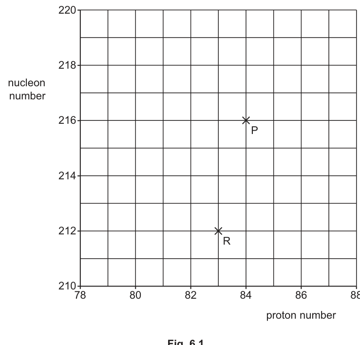
On Fig. 6.1, draw a cross () to show the proton number and nucleon number of Q. Label your cross Q.
Working
For -decay: proton number decreases by and nucleon number decreases by .
From :
Answer
is at (proton number , nucleon number ).
Q at proton number 82, nucleon number 212.
Background Concept
In nuclear decay, the proton number and nucleon number change in specific ways depending on the emitted particle.
For -decay, the nucleus emits an -particle (). Conservation of nucleon number and charge implies:
- decreases by (loss of 4 nucleons)
- decreases by (loss of 2 protons)
So:
Understanding the Question
You are given point on a graph of nucleon number (vertical axis) against proton number (horizontal axis):
- is at , .
Nucleus undergoes -decay to form . You must locate on the same axes.
Approach
Start from for , then apply the fixed changes for -decay: . Plot/identify that coordinate.
Step-by-Step Reasoning
- From the graph, has:
- After -decay:
- Therefore must be at proton number and nucleon number .
Key Takeaways
- -decay always moves you 2 left in and 4 down in .
Common Mistakes
- Subtracting from instead of .
- Subtracting from instead of .
- Swapping axes (mixing up proton number and nucleon number).
Things to Be Careful About
- Ensure you read the axes correctly: proton number is on the horizontal axis, nucleon number on the vertical axis.
- The plotted point should be exactly at the correct grid intersection: .
Working
From the graph: and .
Nucleon number unchanged, proton number increases by decay.
Answer
Particles emitted: (electron) and an antineutrino ().
Electron (β−) and an electron antineutrino (ν̅e).
Background Concept
In decay, the nucleon number stays the same because no nucleons leave the nucleus; instead, a nucleon changes type.
-
In decay: a neutron becomes a proton.
So increases by , unchanged.
-
In decay: a proton becomes a neutron.
So decreases by , unchanged.
Understanding the Question
You have nuclei and with coordinates (proton number, nucleon number). From part (i),
- is at .
The question tells you - is at .
You must state the names of the particles emitted when decays to form .
Approach
Compare and for and :
- If is unchanged, think decay.
- Then check whether increased or decreased to decide between and .
Finally, name the emitted beta particle and the (anti)neutrino that accompanies it.
Step-by-Step Reasoning
-
Compare nucleon numbers:
So this is not decay (which would change by ). It suggests decay.
-
Compare proton numbers:
An increase in by corresponds to decay (neutron proton).
-
In decay, the emitted particles are:
- an electron ()
- an electron antineutrino ()
Key Takeaways
- unchanged and increases by decay.
- decay emits and .
Common Mistakes
- Saying (would make decrease, not increase).
- Forgetting the neutrino/antineutrino.
- Writing “neutrino” when it should be “antineutrino” for decay.
Things to Be Careful About
- Cambridge often expects both particles for 2 marks: the beta particle and the (anti)neutrino.
- Use the correct symbol: for decay; for decay.
Before the -decay, P is travelling at a constant velocity. After the decay, Q has a velocity of at an angle of to the original path of P.
The -particle has a velocity of at an angle of to the original path of P, as shown in Fig. 6.2.
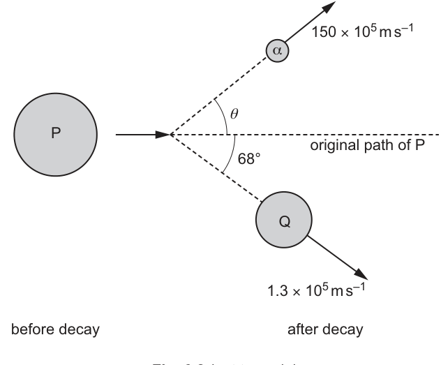
Working
Initial momentum perpendicular to the original path is zero, so after decay:
Using masses nucleon number: .
Answer
25°
Background Concept
Momentum is a vector quantity:
If no external resultant force acts on a system, the total momentum is conserved:
Because momentum is a vector, we often conserve it separately in perpendicular directions (e.g. horizontal and vertical components).
In nuclear decay occurring in free space (or where external forces during the decay are negligible), the nucleus and emitted particle(s) form an isolated system during the decay, so momentum conservation applies.
Understanding the Question
Before decay, nucleus moves along a straight line (take this as the -direction). After decay:
- nucleus has speed at to the original path (downwards in the figure),
- the -particle has speed at angle (upwards in the figure).
You must find the unknown angle using conservation of momentum.
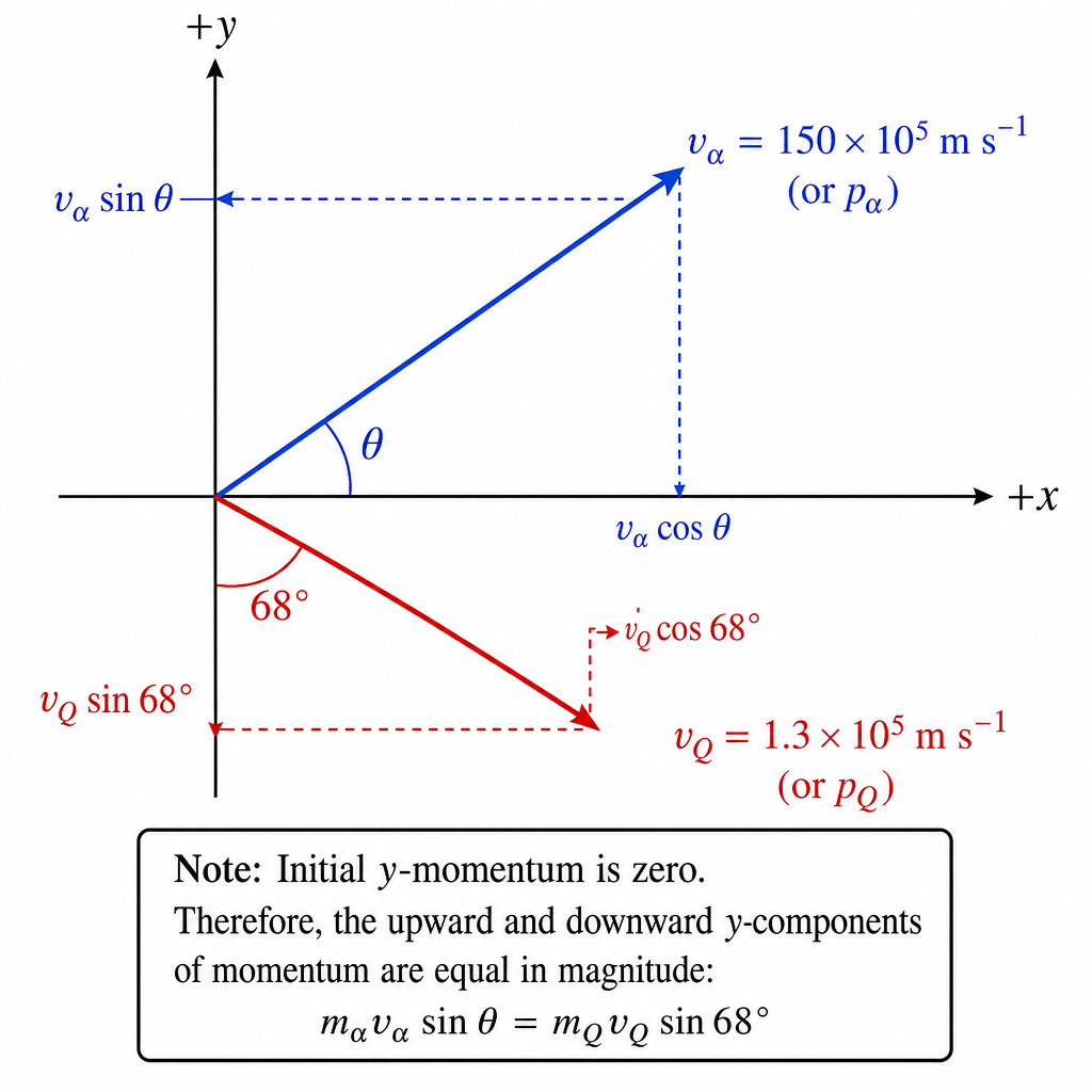
Approach
Use conservation of momentum in the direction perpendicular to the initial motion (the -direction):
- Initially, the -component of momentum is zero (since moves purely along the original path).
- Therefore, after decay, the upward -momentum of the must equal the downward -momentum of .
To form momenta you need masses. In these questions it is standard to take nuclear mass (nucleon number), so
- ,
- (since had and decay reduces by ).
Step-by-Step Reasoning
- Choose axes:
- along original motion of .
- perpendicular to it.
- Write -momentum conservation.
Initial -momentum:
After decay, taking magnitudes and equating upward and downward components:
- Use mass ratio from nucleon numbers.
So
- Evaluate.
- .
- Numerator: ; then .
- Denominator: .
So
Then
Key Takeaways
- Momentum conservation works in each perpendicular direction.
- Using the perpendicular component is often simplest when initial motion is along a straight line.
- In nuclear questions, mass ratios can often be taken from nucleon numbers ().
Common Mistakes
- Conserving momentum using speeds without resolving into components.
- Using instead of for the component perpendicular to the original direction.
- Forgetting to use the mass ratio (treating ).
- Mistyping as or (it is ).
Things to Be Careful About
- Angles are given to the original path, so identify carefully which component is perpendicular.
- Ensure your calculator is in degrees.
- The -components must cancel because the initial -momentum is exactly zero.
Working
For an -particle, .
.
Answer
7.5 × 10^-13 J
Background Concept
Kinetic energy of a particle moving with speed is
This comes from work done to accelerate the mass from rest. It depends on the square of the speed, so getting powers of ten correct is crucial.
For nuclear particles, the mass is often given via the atomic mass unit :
An -particle has mass about .
Understanding the Question
You are given the -particle speed after decay:
You must calculate its kinetic energy in joules using an appropriate mass for the -particle.
Approach
- Convert the mass into kg: .
- Convert the speed into standard form.
- Substitute into and keep track of indices.
Step-by-Step Reasoning
- Mass of :
- Speed:
- Square the speed:
- Substitute:
Multiply the numbers and add indices:
- ,
- .
So
To appropriate s.f.:
Key Takeaways
- Use .
- Convert to kg correctly.
- Squaring a speed in standard form doubles the power of ten.
Common Mistakes
- Using (forgetting the factor ).
- Not converting correctly (it equals , not ).
- Forgetting to square the power of ten when squaring .
Things to Be Careful About
- Keep units consistent: kg and m s give joules.
- Give the final answer in standard form with a sensible number of significant figures.