Physics 9702/21 — October/November 2024
Cambridge AS Level · AS Level Structured Questions · worked solutions for every part, with the mark scheme
Topics Work, Energy and Power · Forces, Density and Pressure · Physical Quantities and Units · Measurement Techniques · Dynamics · Kinematics · +6 more
Answer
Density is mass per unit volume.
Mass per unit volume.
Background Concept
Density, written as , is a material property describing how much mass is packed into a given volume.
It is defined by
where is mass (in ) and is volume (in ). The SI unit of density is .
Understanding the Question
You are asked for the definition of density, so you should give a clear statement (or the defining equation) linking mass and volume.
Approach
State that density is the mass in a unit volume (or write ).
Step-by-Step Reasoning
- Start from the standard definition: density compares mass to volume.
- “Per unit volume” means divide by volume.
- Therefore density is mass per unit volume (equivalently ).
Key Takeaways
- Density is defined as .
- SI unit: .
Common Mistakes
- Saying “density is volume per unit mass” (this is the reciprocal).
- Giving units such as without stating the definition (units alone is not a definition).
Things to Be Careful About
- Use “mass per unit volume” (not weight per unit volume).
- If you write an equation, make sure it is , not .
Fig. 1.1 shows a cuboidal glass block.
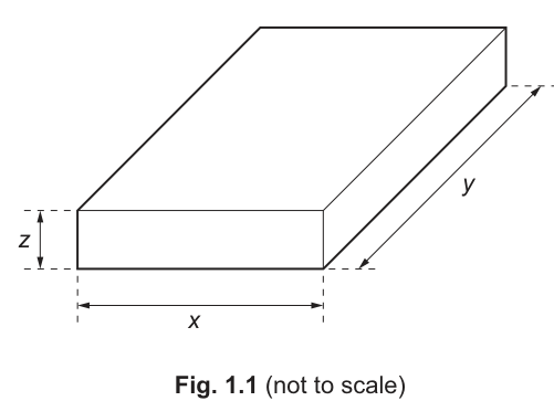
A student measures the mass of the block and the side lengths , and . The measurements are shown in Table 1.1.
Table 1.1
| quantity | measurement |
|---|---|
Working
Convert to metres:
Volume:
Density:
Answer
2.50 × 10^3 kg m^-3
Background Concept
For a uniform solid,
For a cuboid (rectangular block), the volume is the product of its three perpendicular side lengths:
To obtain density in SI units (), mass must be in and volume in . Since the lengths are given in , they must be converted to before calculating .
Understanding the Question
You are given:
- mass
- side lengths , ,
You must find the density of the glass block, using the central values of the measurements.
Approach
- Convert , , from to .
- Compute the volume .
- Use .
- Quote the result with appropriate significant figures and the correct SI unit .
Step-by-Step Reasoning
-
Convert lengths:
-
Calculate volume:
- Calculate density:
The value is sensible for glass (typically around ).
Key Takeaways
- Use and for a cuboid .
- Convert to before calculating in .
- Final unit must be .
Common Mistakes
- Forgetting to convert from to (gives a density too small by a factor of because volume involves ).
- Using instead of multiplying.
- Writing the unit as or (CIE expects ).
Things to Be Careful About
- Converting all three lengths consistently: .
- Significant figures: measurements are typically 3 s.f., so quoting to 3 s.f. is appropriate here.
- Keep track of powers of ten when dividing by a small volume.
Working
For ,
Percentage uncertainty:
Answer
1.3 %
Background Concept
When quantities are multiplied or divided, their fractional (or percentage) uncertainties add.
If
then
This works for powers too: for , the fractional uncertainty is . Here, the density is
so we add the fractional uncertainties in , , , and .
Understanding the Question
You have already calculated in (b)(i). Now you must determine how uncertain that value is, using the uncertainties given with each measured quantity.
The question asks specifically for percentage uncertainty, so your final result should be in .
Approach
- Write down the rule for fractional uncertainty for .
- Calculate each fractional uncertainty: , , , .
- Add them to get .
- Multiply by to convert to a percentage.
Step-by-Step Reasoning
- Start with the relationship:
So,
- Compute each term from the table:
- Mass term:
- Length terms:
Notice the measurement contributes the biggest fractional uncertainty because is the smallest length but has the same absolute uncertainty ().
- Add them:
- Convert to percentage:
Key Takeaways
- For products/quotients, add fractional (percentage) uncertainties.
- The smallest dimension often dominates the uncertainty in volume because its fractional uncertainty is largest.
- Always finish by converting to a percentage if asked.
Common Mistakes
- Subtracting uncertainties because one quantity is in the denominator (you still add fractional uncertainties).
- Forgetting to multiply by to get a percentage.
- Using absolute uncertainties directly (e.g. adding ), which is invalid.
- Converting to metres before calculating uncertainties: not needed, because is the same in any consistent unit.
Things to Be Careful About
- Use the same units for and (here both in is fine).
- Keep enough significant figures during intermediate steps so rounding does not distort the final percentage.
- Check which measurement dominates: this helps spot arithmetic errors (here should contribute most).
The true value of the density of the glass is different from the answer in (b)(i) because of a systematic error in the measurements.
Suggest one possible cause of this systematic error.
Answer
Zero error in the measuring instrument (e.g. balance not zeroed / vernier calipers have a zero error), so all readings are shifted.
Zero error in an instrument (e.g. balance not zeroed or calipers zero error).
Background Concept
A systematic error causes measurements to be consistently too large or too small by a similar amount (or proportion) each time. This shifts the final calculated result away from the true value in a consistent direction.
Common causes include:
- zero error (instrument does not read zero when it should)
- calibration error (scale spacing incorrect)
- consistent parallax due to a fixed viewing angle
This differs from random error, which produces scatter about a mean value and can be reduced by repeats.
Understanding the Question
The density you calculated from the measured , , , and differs from the true density because there is a systematic error in the measurements. You must suggest one plausible cause.
Any one valid cause is sufficient for 1 mark, but it must be systematic (biasing all measurements the same way), not just “human error”.
Approach
Identify a measurement that could be biased in the same direction every time and state the reason. Typical answers refer to:
- the balance (mass)
- the ruler/vernier calipers/micrometer (length)
Step-by-Step Reasoning
- If the balance is not zeroed before measuring, every mass reading has the same offset. That makes consistently too large or too small, so is also consistently too large or too small.
- Similarly, if vernier calipers have a zero error, every length is shifted. Because , this bias affects the volume and therefore density systematically.
Either of these is a valid single cause.
Key Takeaways
- Systematic error = consistent bias, not scatter.
- Zero error and calibration error are the most common systematic errors in basic measurements.
Common Mistakes
- Writing “reaction time” (relevant to timing, and usually random).
- Writing “parallax error” without indicating it is consistent (parallax can be random if viewing angle changes each time).
- Saying “instrument not precise” (precision refers to random uncertainty).
Things to Be Careful About
- Your suggestion must clearly be systematic (same direction each time).
- Link the cause to a specific measurement (mass or one of the lengths) for maximum clarity.
Answer
Linear momentum is the product of mass and velocity:
Linear momentum is the product of mass and velocity, p = mv (a vector).
Background Concept
Momentum is a measure of how difficult it is to change an object’s motion. For an object of mass moving with velocity , its linear momentum is defined by
- is a scalar (in ).
- is a vector (in ).
- Therefore is a vector (in ), which is equivalent to .
Understanding the Question
You are asked to define linear momentum. That means you should give the defining equation and indicate that momentum has direction (i.e. it is a vector).
Approach
State the definition directly using the standard symbol and equation, and (for full credit) make clear it is a vector quantity.
Step-by-Step Reasoning
- Momentum is defined as mass times velocity.
- Because velocity has direction, momentum also has direction.
- Write the definition in vector form: .
Key Takeaways
- Linear momentum is defined by .
- Momentum is a vector; direction matters.
- Units: or .
Common Mistakes
- Writing but not indicating it is a vector when the question is a definition.
- Confusing momentum with force () or kinetic energy ().
Things to Be Careful About
- Use velocity not speed in the definition if you want to emphasise momentum is a vector.
- Ensure the symbol used is (or ) and not pressure (also sometimes written in other contexts).
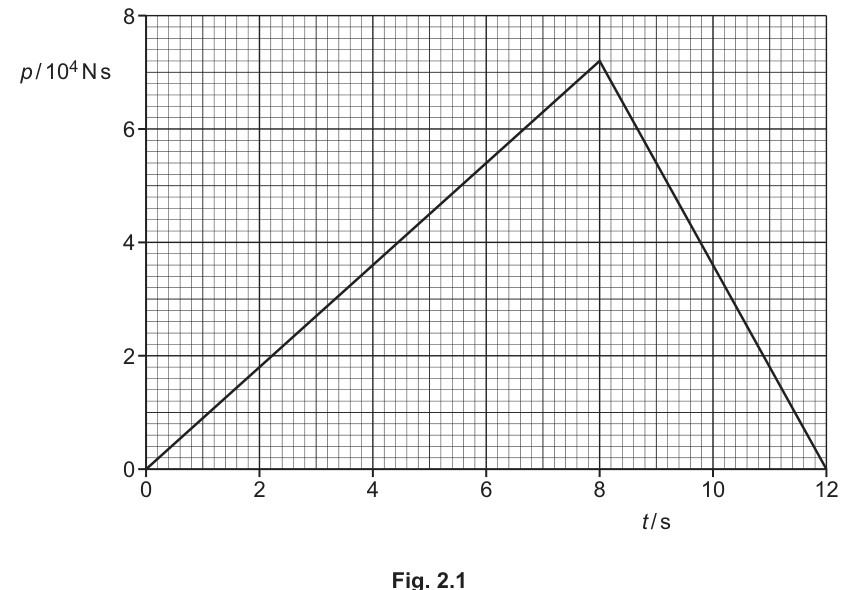
A car of mass is moving in a straight line. Fig. 2.1 shows the variation with time of the momentum of the car.
Working
From graph, .
Answer
40 m s^-1
Background Concept
For motion in a straight line, linear momentum and velocity are related by
If the mass is constant, the speed is found from
The graph gives momentum as a function of time, so the maximum speed occurs when the momentum is at its maximum.
Understanding the Question
- Mass of car: .
- From the momentum–time graph, the largest momentum is at the peak (at ): .
- Required: maximum speed .
Approach
- Read the maximum momentum from the graph.
- Use .
Step-by-Step Reasoning
- Identify the peak momentum on the graph: .
- Substitute into :
- Calculate:
(Using ensures the units reduce to .)
Key Takeaways
- The maximum speed corresponds to the maximum momentum (for constant mass).
- Use and keep track of units.
Common Mistakes
- Forgetting that the vertical axis is in (i.e. misreading as ).
- Using (incorrect).
Things to Be Careful About
- Ensure the factor from the axis label is included.
- Quote speed in .
Working
From (i), .
Answer
1.4 × 10^6 J
Background Concept
Kinetic energy is the energy associated with motion:
If you are given momentum instead of speed, you can find speed using (for constant mass).
Understanding the Question
The graph shows that the car reaches a maximum momentum of , and the car’s mass is . The maximum kinetic energy occurs at the maximum speed (same time as maximum momentum).
Approach
- Find using (or use your answer from part (i)).
- Substitute into .
Step-by-Step Reasoning
- From the peak momentum:
- Kinetic energy at that speed:
- Compute , so
To 2 s.f. (limited by the graph reading ), this is .
Key Takeaways
- Maximum occurs at maximum .
- Combine with when momentum is given.
Common Mistakes
- Using the momentum value directly in the kinetic energy formula without converting to speed.
- Squaring the mass by mistake.
Things to Be Careful About
- Significant figures: the momentum read from the graph is typically 2 s.f., so the final energy should be quoted accordingly.
- Keep units consistent: in and in gives in joules.
Working
From to ,
Answer
at .
5.0 m s^-2
Background Concept
A key link between dynamics and momentum is
where is the resultant force in the direction of motion.
If the mass is constant, and differentiating gives
so you can also use Newton’s second law:
On a momentum–time graph, the gradient equals , i.e. the resultant force.
Understanding the Question
At the car is on the rising straight-line section of the momentum–time graph (from to ). Because this section is a straight line, the gradient (and hence force and acceleration) is constant throughout that interval. You are asked to show the acceleration is .
Approach
- Find the gradient of the straight-line part from to .
- Interpret that gradient as .
- Use .
Step-by-Step Reasoning
- Read endpoints of the first straight segment:
- At , .
- At , .
- Compute gradient:
Units:
so this gradient is a force. Therefore
- Apply Newton’s second law to find acceleration:
Because lies in the same constant-gradient region, at that time.
Key Takeaways
- Gradient of a – graph equals resultant force.
- If mass is constant, .
- Straight-line segment means constant acceleration.
Common Mistakes
- Treating the gradient as acceleration directly (it is force, not acceleration).
- Using instead of from two points on the straight line.
Things to Be Careful About
- Use two well-separated points on the straight-line section to reduce reading error.
- Include the factor from the graph’s momentum scale when calculating .
Working
Distance
Area under – graph area of two triangles:
Answer
240 m
Background Concept
Distance travelled is the area under a velocity–time graph:
Here you are given momentum rather than velocity, but for constant mass:
So
That means: distance = (area under the momentum–time graph) divided by mass.
Understanding the Question
You need the distance travelled from to . The – graph is piecewise linear:
- From to it rises linearly from to .
- From to it falls linearly back to .
So the area under the graph is the sum of two triangles.
Approach
- Find the total area under the – graph by geometry.
- Divide by to convert into .
Step-by-Step Reasoning
- First triangle ( to ):
- Second triangle ( to has base ):
- Total area:
- Convert to distance using :
Unit check: has units , and dividing by gives .
Key Takeaways
- Distance is area under the – graph.
- If given a – graph and is constant, use so distance is area under – divided by .
- Break piecewise-linear graphs into simple shapes.
Common Mistakes
- Treating the area under a momentum–time graph as momentum change (it is not).
- Forgetting to divide the area by the mass.
- Forgetting the factor from the momentum axis.
Things to Be Careful About
- Use the correct base lengths: for the first triangle and for the second.
- Keep consistent powers of ten when multiplying .
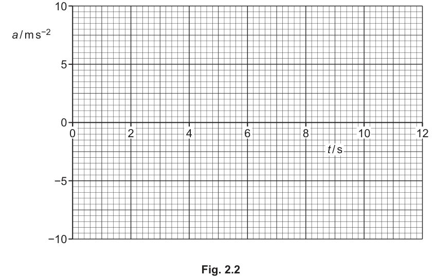
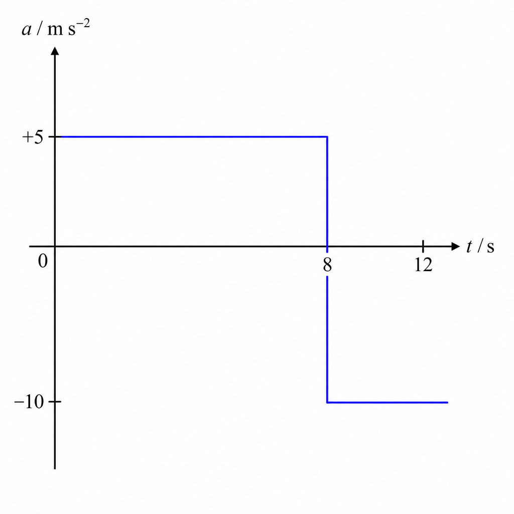
On Fig. 2.2, sketch the variation with time of the acceleration of the car in (b) from to .
Answer
From to : (constant).
From to :
So sketch a horizontal line at from to , then a horizontal line at from to .
a = +5.0 m s^-2 (0–8 s), then a = −10 m s^-2 (8–12 s)
Background Concept
Acceleration is the rate of change of velocity:
With constant mass , momentum is . Differentiating gives
So acceleration can be found directly from a momentum–time graph using
That means: acceleration is proportional to the gradient of the – graph.
Understanding the Question
You are given the momentum–time graph from part (b). It has two straight-line sections:
- to : increases linearly.
- to : decreases linearly back to zero.
A straight-line section has constant gradient, so acceleration will be constant on each time interval. The task is to sketch against from to .
Approach
- Find the gradient for each straight-line section.
- Convert each gradient to acceleration using .
- Sketch a step-like (piecewise constant) acceleration graph with the correct values and time intervals.
Step-by-Step Reasoning
- For to :
Then
So is a horizontal line at from to .
- For to :
Then
So is a horizontal line at from to .
- The sketch should show an abrupt change at (because the slope of the momentum graph changes abruptly there).
Key Takeaways
- Gradient of – graph gives force ().
- With constant mass, .
- Straight-line momentum segments produce constant acceleration segments.
Common Mistakes
- Sketching acceleration increasing linearly (confusing with momentum): acceleration should be constant on each interval because the momentum graph is straight on each interval.
- Getting the sign wrong on the deceleration section (it must be negative because momentum is decreasing).
- Using directly without dividing by .
Things to Be Careful About
- The value is at the lower limit of the provided axis range; place it correctly on the grid.
- The change occurs at exactly; ensure the horizontal segments span the correct time intervals.
Answer
Work done by a force is the product of the force and the displacement in the direction of the force.
Work done = force × displacement in the direction of the force.
Background Concept
Work is the energy transferred when a force causes a displacement. Only the component of displacement along the force contributes to work.
Mathematically, for a constant force causing a displacement at angle to the force,
If the force and displacement are in the same direction, so .
Understanding the Question
The question asks for the meaning of “work done by a force”. It is asking for the definition (not a calculation), so a clear statement linking force, displacement, and direction is needed.
Approach
State that work done depends on displacement along the line of action of the force, and give the standard expression.
Step-by-Step Reasoning
- A force may act at some angle to the displacement.
- Only the component of displacement parallel to the force is effective: .
- Therefore work done is .
Key Takeaways
- Work done is energy transferred by a force.
- Direction matters: use the displacement component in the direction of the force.
Common Mistakes
- Writing “work done = force distance” without specifying “in the direction of the force”.
- Confusing distance moved with displacement component along the force.
Things to Be Careful About
- If force and displacement are not parallel, you must include .
- Work can be negative if the force component is opposite to displacement (not required here but part of the idea).
A block of mass is raised vertically at constant speed. The vertical height gained by the block is , as shown in Fig. 3.1.
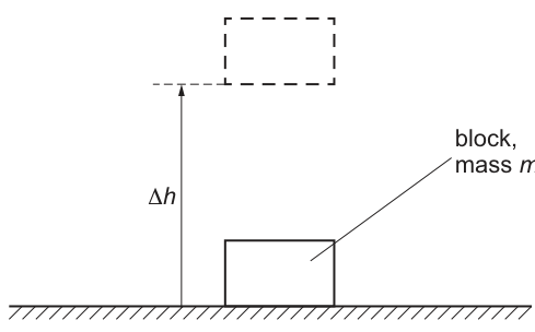
Derive an expression, in terms of and , for the change in gravitational potential energy of the block. State the meaning of any other symbols you use.
Working
Weight of block .
Work done against weight in raising through height :
This work done equals the increase in gravitational potential energy, so
where is the acceleration of free fall.
Answer
(\Delta E_P = mg,\Delta h) (where (g) is gravitational field strength / acceleration of free fall).
Background Concept
Near the Earth’s surface, the weight of a mass is approximately constant and equal to , where is the acceleration of free fall (gravitational field strength).
The change in gravitational potential energy is the energy gained when an object is raised. For a constant weight, it equals the work done against gravity:
Work done by a constant force is
when the displacement is in the direction of the force.
Understanding the Question
A block of mass is lifted vertically through a height at constant speed. The question asks you to derive an expression for the change in gravitational potential energy in terms of and , and to define any other symbol used (here, ).
Approach
- Identify the force opposing the lift: the weight .
- Since the block moves up at constant speed, the energy transferred by the lifting force is not increasing kinetic energy; it goes into gravitational potential energy.
- Use with and .
Step-by-Step Reasoning
- The weight of the block is
- The block is raised vertically by , so the displacement in the direction of weight (downward) is opposite; equivalently, the work done against weight uses the magnitude and distance :
- At constant speed, kinetic energy does not change, so the work done against gravity appears as an increase in gravitational potential energy:
Key Takeaways
- equals work done against weight for vertical lifting near Earth.
- Constant speed implies no change in kinetic energy.
Common Mistakes
- Using (confusing with kinetic energy).
- Forgetting to define .
- Using instead of when the question specifies a height gain.
Things to Be Careful About
- should be stated as acceleration of free fall / gravitational field strength (units or ).
- The derivation assumes is constant over the height change (valid for ordinary lab-scale heights).
An electric motor has an input power of . The motor takes to lift a load of weight at constant speed through a vertical height of . Resistive forces are negligible.
Working
Work done on the load:
Answer
36 kJ
Background Concept
Work done by a force is
when the force and displacement are in the same direction. In lifting at constant speed with negligible resistance, the motor’s force on the load balances the weight, so the work done equals the gain in gravitational potential energy.
Understanding the Question
The load has weight and is lifted vertically through . The question asks you to show the motor does of work on the load in minute; the time is not actually needed for this part because work depends on force and distance.
Approach
Use with and , then convert from joules to kilojoules.
Step-by-Step Reasoning
- Multiply force by distance:
- Convert to kilojoules using :
Key Takeaways
- Work done in lifting: .
- Time is irrelevant for work; time matters for power.
Common Mistakes
- Dividing by time in this part (that gives power, not work).
- Using mass instead of weight without converting.
Things to Be Careful About
- Ensure the height is in metres and force in newtons so work is in joules.
- State the final value as as requested.
Working
Useful output power:
Answer
600 W
Background Concept
Power is the rate of doing work (energy transfer per unit time):
If the useful work is the increase in gravitational potential energy of the load, then the useful output power is the useful work divided by the time taken.
Understanding the Question
In minute the motor lifts a load through at constant speed. From part (c)(i), the useful work done on the load is . The question asks for the useful output power of the motor (power delivered to the load).
Approach
Convert minute to seconds, then apply using the useful work.
Step-by-Step Reasoning
- Convert time:
- Use :
So the useful output power is .
Key Takeaways
- Power depends on both energy transferred and the time taken.
- Always convert minutes to seconds when working in SI.
Common Mistakes
- Using the input power as the output power.
- Forgetting to convert into joules.
Things to Be Careful About
- The “useful output power” is the power delivered to the load, not the electrical input power.
- Keep consistent SI units to avoid factor-of-60 or factor-of-1000 errors.
Use your answer in (c)(ii) to determine the efficiency of the motor.
efficiency = ______
Working
Answer
(or )
0.67 (≈ 67%)
Background Concept
Efficiency measures how much of the input energy (or power) becomes useful output:
For steady operation, you can use power values:
Understanding the Question
The motor’s input power is . From (c)(ii), the useful output power (lifting the load) is . The question asks for the efficiency.
Approach
Take the ratio and express as a decimal (or percentage).
Step-by-Step Reasoning
- Substitute values:
- Round suitably:
Key Takeaways
- Efficiency is always less than or equal to .
- Using power is appropriate when input and output occur over the same time interval.
Common Mistakes
- Inverting the ratio (), giving a value greater than .
- Mixing work and power inconsistently (e.g. using input power with output work).
Things to Be Careful About
- Quote efficiency either as a decimal or a percentage; do not include units.
- Keep enough significant figures consistent with given data (here, is appropriate).
Some of the power wasted in the motor is dissipated by the resistance of its coil. This dissipated power is .
The coil of the motor is made from wire of total length . The wire has a cross-sectional area of and is made from metal of resistivity .
Calculate the current in the coil.
current = ______
Working
Resistance of coil:
Dissipated power:
Answer
4.3 A
Background Concept
The resistance of a uniform wire is related to its material and dimensions by
where is resistivity (), is length (m), and is cross-sectional area ().
Electrical power dissipated as heating in a resistor can be written as
This is appropriate when the given power is specifically the power lost in the resistance of the coil.
Understanding the Question
We are told that the wasted (dissipated) power in the motor coil is . The coil is made from wire of length , area , resistivity . We must find the current in the coil.
So we need:
- the coil resistance from ;
- then use to solve for .
Approach
- Compute using the resistivity formula (all values are already in SI).
- Rearrange to .
- Substitute and round sensibly.
Step-by-Step Reasoning
- Resistance of the coil:
Substitute:
Notice the cancels, leaving a value of order :
- Use the resistive power equation:
Rearrange:
Substitute and :
Key Takeaways
- Use when resistance is determined by geometry/material.
- When power loss in a resistor is given, is often the quickest route to current.
Common Mistakes
- Using without knowing across the coil.
- Forgetting the square root when rearranging .
- Mis-handling powers of ten in (the terms cancel here).
Things to Be Careful About
- Ensure is in , in m, in so that is in .
- Quote current to an appropriate number of significant figures (here, is reasonable).
Answer
Young modulus is the ratio of tensile stress to tensile strain (within the limit of proportionality).
Young modulus is the ratio of tensile stress to tensile strain (within the limit of proportionality).
Background Concept
When a wire is stretched by a tensile force, it experiences:
- Tensile stress: force per unit cross-sectional area,
- Tensile strain: fractional change in length,
In the linear-elastic region (up to the limit of proportionality), stress is proportional to strain. The constant of proportionality is the Young modulus :
Understanding the Question
You are asked to define Young modulus. That means you must give the ratio and indicate it applies where the material obeys Hooke’s law (linear relationship).
Approach
Give the standard definition:
- write stress and strain (can be in words),
- state stress/strain, and (ideally) that it is within the limit of proportionality.
Step-by-Step Reasoning
- Young modulus compares how much stress is needed to produce a given strain.
- In the region where the graph of stress against strain is a straight line, the ratio is constant.
- Therefore,
Key Takeaways
- measures stiffness of a material in extension.
- Definition must include stress/strain and the linear (proportional) region.
Common Mistakes
- Writing (that is stiffness/spring constant for a particular sample, not a material property).
- Forgetting strain is fractional change in length.
- Not indicating the condition “within limit of proportionality”.
Things to Be Careful About
- Young modulus depends on the material, not the dimensions, whereas depends on wire geometry.
- Use correct terms: tensile stress and tensile strain.
A metal wire P that obeys Hooke’s law is stretched within its limit of proportionality.
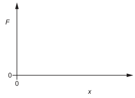
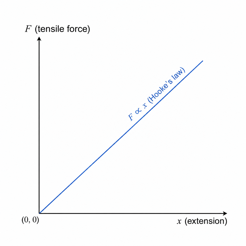
Answer
A straight line through the origin with constant positive gradient ().
Straight line through the origin (F ∝ x).
Background Concept
Hooke’s law in extension states that, up to the limit of proportionality,
where:
- is the tensile force,
- is the extension,
- is the stiffness (spring constant) of that wire.
So is directly proportional to .
Understanding the Question
The wire obeys Hooke’s law and is stretched within the proportional limit. You must sketch the graph of tensile force against extension .
Approach
Use :
- direct proportion implies a straight line,
- when , , so it passes through the origin,
- gradient is constant and positive.
Step-by-Step Reasoning
- Start at because zero extension means no stretching force.
- Draw a straight line with positive slope because increasing extension requires increasing force.
- No curvature and no change of gradient because we are within the proportional limit.
Key Takeaways
- In the Hooke’s law region, – is a straight line through the origin.
Common Mistakes
- Drawing a curve (that would indicate leaving the proportional region).
- Drawing a line that does not pass through the origin.
- Confusing extension with total length.
Things to Be Careful About
- The phrase “within its limit of proportionality” is the key clue that the graph must be linear.
- Axes must be correctly labelled (vertical) and (horizontal).
Answer
The spring constant / stiffness of the wire.
Spring constant (stiffness) k.
Background Concept
For a linear force–extension relationship,
Comparing this with the straight-line form , the gradient of the – graph is .
Understanding the Question
You are asked to name the physical quantity represented by the gradient of the line on a graph of tensile force against extension .
Approach
Use the equation that matches the axes: is on the vertical axis and on the horizontal axis, so
and identify this with from .
Step-by-Step Reasoning
- The gradient is
- From Hooke’s law, is constant and equals .
- Therefore the gradient represents the stiffness (spring constant) .
Key Takeaways
- On an vs graph, gradient .
Common Mistakes
- Saying “Young modulus” (Young modulus comes from stress–strain, not force–extension).
- Using instead of .
Things to Be Careful About
- is a property of the particular wire sample (depends on and ), unlike Young modulus which is a material property.
Answer
The work done in stretching the wire (elastic potential energy stored).
Work done in stretching the wire (elastic potential energy stored).
Background Concept
Work done by a variable force is the area under a force–displacement graph:
On a graph of against extension , the area under the line from to the final extension is the work done stretching the wire. In elastic deformation, this work is stored as elastic potential energy.
For Hooke’s law (), the area is a triangle:
Understanding the Question
The graph is tensile force vs extension . You are asked what the area under the line represents.
Approach
Use the general idea: area under an – graph gives work done. Since stretching is elastic (within proportional limit), that work becomes elastic potential energy.
Step-by-Step Reasoning
- A small extension requires work .
- Summing (integrating) over the whole extension gives total work:
- Graphically, this is the area under the – line.
- Because the wire remains elastic, this equals the elastic potential energy stored.
Key Takeaways
- Area under – graph = work done = elastic potential energy (if deformation is elastic).
Common Mistakes
- Saying the area is the spring constant (that is the gradient).
- Confusing the area with momentum/impulse (those involve force–time graphs).
Things to Be Careful About
- The “energy stored” statement is valid here because the question specifies extension within the limit of proportionality (elastic behaviour).
Another wire Q is made from a metal that has twice the Young modulus of the metal of wire P in (b). Wire Q has the same volume as wire P but has double the cross-sectional area of wire P.
The two wires are extended by equal tensile forces within their limits of proportionality.
State and explain how the extension of wire Q compares with the extension of wire P.
Working
For a wire in the proportional region,
Same volume: , and so
Also . Hence
Answer
Wire Q extends to one-eighth of the extension of wire P: .
x_Q = (1/8) x_P (wire Q extends one-eighth as much as wire P).
Background Concept
In the linear-elastic (Hooke’s law) region for a wire, combining definitions of stress and strain gives the standard extension formula:
Rearranging,
So extension increases with force and original length , and decreases with cross-sectional area and Young modulus .
Also, wire volume is
If volume is fixed and the area increases, the length must decrease.
Understanding the Question
You have two wires:
- Wire P: area , length , Young modulus .
- Wire Q: Young modulus is twice: .
- Same volume as P, but double cross-sectional area: .
- Both stretched by the same tensile force within proportional limits.
You must compare extensions and and explain.
Approach
- Use same-volume condition to find how compares with .
- Use for each wire.
- Form a ratio so cancels and only geometry/material factors remain.
Step-by-Step Reasoning
1) Use equal volumes
Same volume means:
Given :
So Q is half as long.
2) Use the extension formula
For P:
For Q:
3) Compare using a ratio
Now substitute the given comparisons:
So
Therefore wire Q extends one-eighth as much as wire P under the same force.
Key Takeaways
- For a wire, .
- Same volume gives constant, so changing changes .
- Increasing and both reduce extension.
Common Mistakes
- Assuming even though the volume is the same.
- Only accounting for the change in (getting ) and forgetting and changes.
- Using (incorrect rearrangement).
Things to Be Careful About
- The wire sample stiffness depends on both material property () and geometry ( and ).
- When forming ratios, cancel the common force to avoid unnecessary algebra errors.
- Work strictly within “limits of proportionality” so the linear relation applies.
Potassium-40 () undergoes decay to form a nuclide of element X. Particle Z is emitted during the decay. The equation for the decay is shown.
Working
In decay, nucleon number is conserved, so .
Charge (proton number) is conserved:
so .
For a particle:
Answer
P = 40, Q = 20, R = 0, S = -1
Background Concept
In any nuclear decay equation, two key quantities are conserved:
- Nucleon (mass) number, : total number of protons + neutrons in the nucleus.
- Proton (atomic) number, : number of protons (and hence the nuclear charge in units of ).
For decay, a neutron in the nucleus changes into a proton and emits an electron (the particle) and an electron antineutrino:
So, for the nucleus as a whole:
- stays the same (a neutron becomes a proton: still one nucleon).
- increases by 1 (because there is one extra proton).
A particle is an electron, written in nuclear notation as:
Understanding the Question
You are given:
and asked to state .
So you must use conservation of nucleon number and proton number to fill the unknowns.
Approach
- Use conservation of nucleon number () to find (and for the beta particle).
- Use conservation of proton number () to find (and for the beta particle).
- Recall the standard nuclear notation for .
Step-by-Step Reasoning
1) Nucleon number conservation
- Potassium-40 has .
- A particle has .
- Neutrinos/antineutrinos also have .
So the daughter nuclide must keep :
Also, for the particle:
2) Proton number (charge) conservation
- Potassium-40 has .
- A particle has .
- Neutrinos/antineutrinos have .
So:
and for the beta particle:
Therefore:
(You could also note that increasing from 19 to 20 means the element becomes calcium, but the question only asks for .)
Key Takeaways
- Balance mass number and proton number on both sides of any nuclear equation.
- In decay: unchanged, increases by 1.
- has nuclear notation .
Common Mistakes
- Writing as (confusing it with a neutron/proton).
- Changing the mass number in decay (it should stay the same).
- Forgetting the negative proton number () for the emitted electron.
Things to Be Careful About
- Always treat as a signed quantity for emitted particles: electron has .
- Neutrinos/antineutrinos carry no nucleon number and no charge, so they do not affect or balancing.
Answer
Particle Z is an electron antineutrino, .
electron antineutrino
Background Concept
In decay, a neutron changes into a proton. To conserve several quantities (including lepton number), an electron and an electron antineutrino are emitted:
The neutrino/antineutrino has:
- charge
- (almost) zero mass
- interacts very weakly with matter
Understanding the Question
The decay equation shows an extra particle emitted alongside the particle. The question asks for the name of .
Approach
Recall the standard products of decay and identify the accompanying neutrino-type particle.
Step-by-Step Reasoning
- A particle is an electron, .
- In decay, the accompanying neutral particle is the electron antineutrino.
So is .
Key Takeaways
- decay emits an electron and an electron antineutrino.
Common Mistakes
- Writing “neutrino” instead of “antineutrino” for decay.
- Naming it as a gamma photon (gamma emission is a different process).
Things to Be Careful About
- At A Level, it is expected to distinguish from for versus decay.
State the name of the class of fundamental particle to which both the particle and particle Z belong.
Answer
They are both leptons.
leptons
Background Concept
Fundamental particles at this level are grouped into leptons and hadrons:
- Leptons: electron , muon , tau , and their associated neutrinos (and antiparticles). They do not experience the strong interaction.
- Hadrons: particles made of quarks (baryons and mesons) that do experience the strong interaction.
A particle is an electron, and neutrinos/antineutrinos are also leptons.
Understanding the Question
You have identified (from earlier parts) that the particle is an electron and particle is an electron antineutrino. The question asks what class of fundamental particle they both belong to.
Approach
Recognise each particle and then state the shared classification.
Step-by-Step Reasoning
- is an electron , which is a lepton.
- is an electron antineutrino , which is also a lepton.
Therefore both are leptons.
Key Takeaways
- Electrons and neutrinos (and their antiparticles) are leptons.
Common Mistakes
- Saying “hadrons” because the decay happens in a nucleus (the nucleus contains hadrons, but the emitted and neutrino are leptons).
- Confusing “lepton” with “leptons and antileptons” (antiparticles are still in the lepton family).
Things to Be Careful About
- The classification is about the particle type (lepton/hadron), not whether it comes from the nucleus.
Working
An -particle has protons and neutrons.
Proton: .
Neutron: .
Total quarks:
Answer
Quark composition: .
6u + 6d
Background Concept
Quarks combine to form hadrons:
- A proton has quark composition (two up quarks and one down quark).
- A neutron has quark composition (one up quark and two down quarks).
An alpha particle () is the nucleus of helium-4, containing:
- 2 protons
- 2 neutrons
To find the quark composition of a nucleus, you add together the quarks in all its protons and neutrons.
Understanding the Question
You are asked for the quark composition of an alpha particle. Since an alpha particle is made of 2 protons and 2 neutrons, you must express it in terms of the numbers of up () and down () quarks.
Approach
- Write the quark content for one proton and one neutron.
- Multiply by how many protons/neutrons are in the alpha particle.
- Add the totals of and quarks.
Step-by-Step Reasoning
1) Identify nucleons in an alpha particle
- : .
2) Write quark compositions
3) Count quarks from the two protons
Two protons give:
- up quarks:
- down quarks:
So: .
4) Count quarks from the two neutrons
Two neutrons give:
- up quarks:
- down quarks:
So: .
5) Total quarks in the alpha particle
Add them:
So the alpha particle contains six up quarks and six down quarks.
Key Takeaways
- Use and .
- For composite particles like nuclei, multiply and add quark counts across all nucleons.
Common Mistakes
- Forgetting that an alpha particle has two neutrons as well as two protons.
- Writing (counting only one proton + one neutron).
- Mixing in electrons (the alpha particle is the nucleus only, not the whole atom).
Things to Be Careful About
- State your answer clearly as numbers of quarks, e.g. (either order is fine).
- Do not include antiquarks here: protons and neutrons are baryons made of three quarks (not antiquarks).
Two coherent sources X and Y of microwaves of frequency are a distance of apart in a vacuum, as shown in Fig. 6.1.
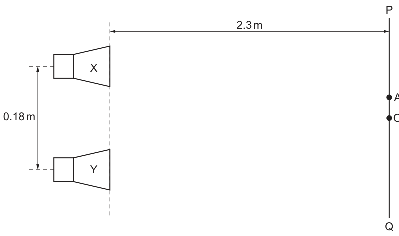
There is a phase difference of between the waves emitted at the two sources.
A microwave detector moves along the line PQ, which is parallel to the line joining the two sources and away from it.
Point O is on the line PQ at a position that is equidistant from the two sources.
Point A is the position on line PQ where the intensity of the microwaves is the greatest.
Answer
At the path lengths from and are equal, so the path difference is .
Therefore the phase difference at is still , not (or ), so the waves do not arrive in phase and the intensity at is not a maximum.
At O the path difference is zero so the phase difference remains 90°, hence not in phase and not a maximum.
Background Concept
For two coherent sources, the intensity at a point depends on the phase difference (\phi) between the two waves when they arrive at that point.
- Constructive interference (maximum intensity): waves arrive in phase
- Destructive interference (minimum intensity): waves arrive in antiphase
The total phase difference at the detector comes from two contributions:
- Any initial phase difference at the sources.
- Additional phase difference caused by a path difference (\Delta x) between the two routes to the detector.
A path difference of one wavelength (\lambda) corresponds to (360^\circ) of phase.
So a path difference (\Delta x) produces phase difference
Understanding the Question
Point (O) on line (PQ) is equidistant from sources (X) and (Y). That means the two microwaves travel the same distance to reach (O). However, the question states that the sources emit with a phase difference of (90^\circ). The task is to explain why, despite equal path lengths, (O) is not where the intensity is greatest.
Approach
Use the interference condition for a maximum: the waves must arrive in phase. Check what the phase difference is at (O):
- compute/identify path difference at (O)
- add it to the given source phase difference
- compare the result with (0^\circ) (maximum condition)
Step-by-Step Reasoning
-
At (O), the distances from (X) and (Y) to (O) are the same (by definition of equidistant).
Hence path difference
- If (\Delta x = 0), then the phase difference due to the path is
- Therefore, the phase difference at (O) is just the original source phase difference:
- (90^\circ) is neither (0^\circ) (in phase) nor (180^\circ) (antiphase). The waves do not fully reinforce each other, so (O) cannot be a point of greatest intensity.
Key Takeaways
- Equal distances (zero path difference) do not guarantee a maximum if the sources are not emitting in phase.
- Total phase difference = (source phase difference) + (path-induced phase difference).
Common Mistakes
- Assuming “equidistant from both sources” automatically means maximum intensity.
- Forgetting to include the given (90^\circ) phase difference at emission.
Things to Be Careful About
- Always distinguish between path difference (geometry) and phase difference at the source (given property of emission).
- The condition for maximum is (0^\circ) (mod (360^\circ)), not “small phase difference”.
On Fig. 6.1, draw a cross () to show the position of the point on line PQ where the intensity minimum that is the closest to point O occurs. Label this point B.
Working
At , phase difference .
For the nearest minimum, total phase difference , so extra phase needed is .
Hence path difference
So point is the closest point on where the path to one source is longer than to the other by .
Since the nearest maximum () is on the opposite side of , is on on the opposite side of from .
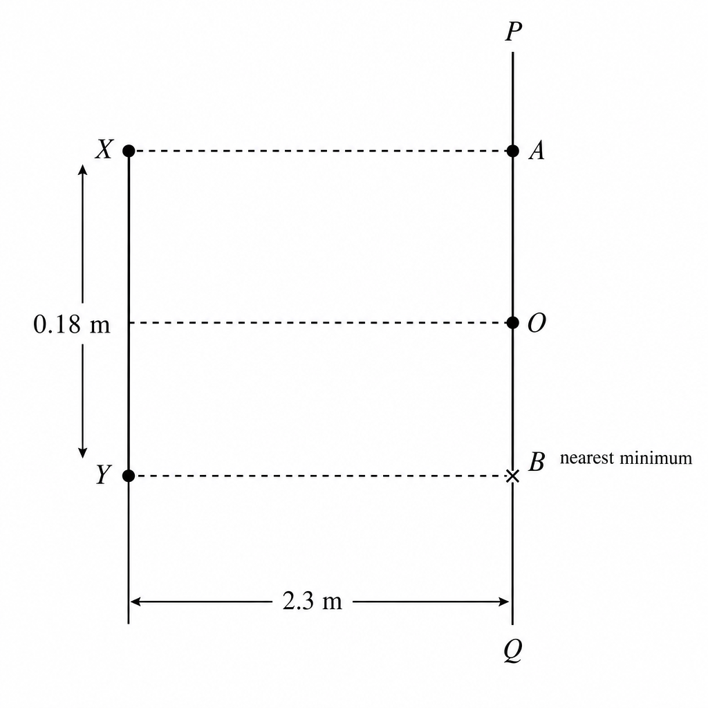
Answer
is on line closest to on the opposite side of from (so that the path difference is ).
Point B is the nearest point on PQ to O on the opposite side of O from A (path difference = λ/4).
Background Concept
Interference minima and maxima depend on the total phase difference at the observation point:
with
A minimum occurs when
Here (\phi_{\text{source}} = 90^\circ), so the “usual” positions of maxima/minima are shifted compared with in-phase sources.
Understanding the Question
You must mark the position (B) on the detector line (PQ) that is the closest minimum to (O). At (O), the detector is equidistant from (X) and (Y), so the path difference is zero. Because the sources are already (90^\circ) out of phase, (O) is not a maximum, and nearby points will give the first minimum and first maximum.
The diagram also shows a point (A) above (O) which is the location of greatest intensity (a maximum). The closest minimum will be on the opposite side of (O) from that maximum.
Approach
- Start from the phase difference at (O): (90^\circ).
- For a minimum, set total phase difference to (180^\circ).
- Find the extra phase needed and convert it to path difference (\Delta x).
- Decide where along (PQ) this condition is met relative to (O) and (A).
Step-by-Step Reasoning
- At (O): (\Delta x = 0), so (\phi_{\text{total}} = 90^\circ).
- Nearest minimum requires:
So the additional phase needed from the path difference is
- Convert (90^\circ) into a fraction of a wavelength:
- This means (B) is the closest point to (O) where one path is longer than the other by (\lambda/4).
- Since point (A) is the maximum on one side of (O), the nearest minimum occurs on the other side (because a maximum and a minimum correspond to opposite signs of the required path difference when there is a fixed source phase).
Key Takeaways
- With a non-zero source phase difference, the central equidistant point is not necessarily a maximum.
- To find minima/maxima, use total phase difference, not just geometry.
- A phase change of (90^\circ) corresponds to a path difference of (\lambda/4).
Common Mistakes
- Putting the minimum at (O) because “equal distances means cancellation” (it doesn’t here).
- Using the usual in-phase conditions (max at (\Delta x = 0)) without adjusting for the (90^\circ) source phase difference.
- Confusing the spacing of fringes (which stays the same) with the shift of the whole pattern (which changes).
Things to Be Careful About
- The question asks for the closest minimum: choose the smallest magnitude path difference solution (here (\lambda/4), not (5\lambda/4), etc.).
- On a diagram, you cannot show exact distances numerically, but you must place (B) correctly relative to (O) and (A).
Working
For microwaves in vacuum, .
Answer
0.012 m
Background Concept
All waves satisfy the wave equation
where:
- (v) is wave speed ((\text{m s}^{-1}))
- (f) is frequency ((\text{Hz}))
- (\lambda) is wavelength ((\text{m}))
Electromagnetic waves (including microwaves) travel in a vacuum at the speed of light
So in vacuum:
Understanding the Question
You are given the microwave frequency (f = 2.5 \times 10^{10}\ \text{Hz}) and told the microwaves travel in a vacuum, so their speed is (c). The task is to show the wavelength is (0.012\ \text{m}).
Approach
Use (\lambda = c/f). Substitute (c = 3.0 \times 10^8) and the given (f), then simplify the powers of ten and the numerical factor.
Step-by-Step Reasoning
- Write the equation:
- Substitute:
- Separate numbers and powers of ten:
- Convert to decimal:
Key Takeaways
- In vacuum, microwaves travel at (c).
- Wavelength is found from (\lambda = c/f).
Common Mistakes
- Using (v = 340\ \text{m s}^{-1}) (speed of sound) instead of (c).
- Power-of-ten errors, e.g. using (10^{10}/10^8) instead of (10^8/10^{10}).
Things to Be Careful About
- Keep units consistent: (c) in (\text{m s}^{-1}) and (f) in (\text{s}^{-1}) gives (\lambda) in metres.
- When dividing powers of ten: (10^a/10^b = 10^{a-b}).
For point A on line PQ, determine the difference in the distances travelled by the microwaves from X and the microwaves from Y.
= ______
Working
For a maximum at , total phase difference must be (mod ).
Source phase difference is , so the path must provide (equivalently ).
Smallest magnitude path difference is
With ,
Answer
0.0030 m
Background Concept
For two-source interference, the brightness/intensity depends on the total phase difference between waves at the observation point.
If the sources are not in phase initially, then
A maximum occurs when
The path phase difference comes from path difference (\Delta x):
Understanding the Question
Point (A) is stated to be where the intensity is greatest (a maximum) on the detector line (PQ). The sources emit with a fixed phase difference (90^\circ). You are asked to find the path difference (\Delta x) between the distances travelled from (X) and from (Y) to reach (A).
Because (A) is the closest maximum to (O) on the diagram, the corresponding path difference should be the smallest one that satisfies the maximum condition.
Approach
Set the maximum condition for total phase difference. Since the sources already differ by (90^\circ), the path difference must supply an additional phase shift that brings the total to (0^\circ) (or (360^\circ)). Convert that required phase shift into (\Delta x) using fractions of (\lambda).
Step-by-Step Reasoning
- Given source phase difference:
- For a maximum:
So the path must contribute either (-90^\circ) or equivalently (270^\circ). The smallest magnitude phase shift is (90^\circ), corresponding to a quarter wavelength path difference.
- Convert (90^\circ) to a path difference:
- Using (\lambda = 0.012\ \text{m}):
(If you track sign, (A) would correspond to (\Delta x = -\lambda/4) or (+3\lambda/4) depending on which source’s wave arrives ahead. The question asks for the difference in distances; typically the magnitude (\lambda/4) is sufficient.)
Key Takeaways
- Maxima occur when total phase difference is (0^\circ) (mod (360^\circ)), even if sources are initially out of phase.
- A (90^\circ) phase adjustment corresponds to a path difference of (\lambda/4).
Common Mistakes
- Using (\Delta x = 0) for a maximum (only true if sources start in phase).
- Using the destructive condition ((180^\circ)) instead of constructive.
Things to Be Careful About
- The fringe spacing formula in the next part is unaffected by the initial phase, but the positions of maxima/minima shift.
- Be consistent about whether (\Delta x) is a signed difference or an absolute difference; many mark schemes accept the magnitude for this style of question.
Use the formula for the double-slit interference of light to calculate the distance between adjacent intensity maxima on line PQ.
distance = ______
Working
Using double-slit fringe spacing
with , , :
Answer
distance
0.15 m
Background Concept
For two coherent sources (or a double slit) separated by distance (a), with a screen (or observation line) a perpendicular distance (D) away, the separation (s) between adjacent bright fringes is
This comes from the small-angle approximation where the path difference changes approximately linearly with position along the screen.
A key point: an initial phase difference between sources shifts the entire pattern, but it does not change the spacing (s) between adjacent maxima.
Understanding the Question
You are told:
- source separation (a = 0.18\ \text{m})
- detector line (PQ) is parallel to the sources and (D = 2.3\ \text{m}) away
- wavelength from earlier part (\lambda = 0.012\ \text{m})
You must calculate the distance along (PQ) between adjacent intensity maxima.
Approach
Use the standard fringe spacing equation (s = \lambda D/a) and substitute the given values in metres.
Step-by-Step Reasoning
- Write the formula:
- Substitute:
- Calculate:
- Round appropriately (typically 2 s.f. here):
Key Takeaways
- Fringe spacing for two-source/double-slit interference is (\lambda D/a).
- A fixed source phase difference shifts where the maxima occur, but not the distance between them.
Common Mistakes
- Using (a) and (D) the wrong way round (writing (aD/\lambda)).
- Forgetting all distances must be in metres.
- Thinking the (90^\circ) phase difference changes the spacing; it only shifts the pattern.
Things to Be Careful About
- The formula is derived using small angles; it is appropriate here because (D) (2.3 m) is much larger than (a) (0.18 m), so angles to fringes are small.
- Quote the final answer to a sensible number of significant figures consistent with the given data.
Fig. 7.1 shows two resistors connected in series with a cell of electromotive force (e.m.f.) and internal resistance .
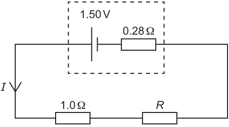
One of the resistors has resistance . The other resistor has resistance . The terminal potential difference (p.d.) across the cell is .
Working
Lost volts across internal resistance:
Answer
0.50 A
Background Concept
A real cell can be modelled as an ideal source of e.m.f. in series with an internal resistance . When a current flows, there is a potential drop inside the cell equal to (often called the “lost volts”).
The terminal potential difference across the cell’s terminals is then
This is smaller than when the cell is delivering current.
Understanding the Question
You are told the e.m.f. of the cell (), its internal resistance (), and the terminal p.d. while the external circuit is connected (). The circuit current is the same everywhere because the external resistors are in series.
The question asks you to show that this current is .
Approach
Use the internal resistance model: first find the “lost volts” , then use to calculate .
Step-by-Step Reasoning
- Find the drop across the internal resistance:
- Apply Ohm’s law to the internal resistance (since the same current flows through it):
- Rearrange and substitute:
Key Takeaways
- Terminal p.d. is reduced from e.m.f. by the internal drop .
- The “lost volts” method is often the quickest way to find when , , and are given.
Common Mistakes
- Using with as the external resistance before finding (you are not given yet).
- Writing (wrong sign when the cell supplies current).
Things to Be Careful About
- Keep track of which voltage is terminal p.d. () and which is e.m.f. ().
- Ensure the internal resistance is in and current comes out in .
Working
Terminal p.d. across external resistors:
Answer
Combined resistance
2.72 Ω
Background Concept
For components in series, the same current flows through each component. The total resistance of the external circuit can be treated as a single equivalent resistance .
If the terminal potential difference across the external circuit is and the series current is , then by Ohm’s law:
Understanding the Question
In Fig. 7.1, the terminal p.d. across the cell is . This is also the p.d. across the entire external circuit (the two resistors in series), because that external circuit is connected directly across the cell terminals.
From (a)(i), . The question asks for the combined (equivalent) resistance of the two series resistors.
Approach
Treat the two external resistors as a single equivalent resistance and use .
Step-by-Step Reasoning
- Identify that is across the external resistors together.
- Apply Ohm’s law:
- Substitute values:
Key Takeaways
- Terminal p.d. is the p.d. across the external circuit connected to the cell.
- Equivalent resistance for the external circuit can be found directly from when is the terminal p.d.
Common Mistakes
- Using the e.m.f. instead of the terminal p.d. when calculating the external resistance.
- Adding internal resistance to the external resistance here (the question asks only for the two resistors).
Things to Be Careful About
- Use the current found in (a)(i); do not recalculate it from other assumptions.
- Quote resistance with unit and to a sensible number of significant figures consistent with the data (here is fine).
Working
In series:
Answer
1.72 Ω
Background Concept
For resistors in series, resistances add:
Understanding the Question
From (a)(ii), the combined resistance of the two series resistors is . One resistor is known to be , and the other is . You are asked to find .
Approach
Use the series rule: total equals the sum. Rearrange to isolate .
Step-by-Step Reasoning
- Write the series relationship:
- Substitute :
- Rearrange:
Key Takeaways
- Series resistors add directly.
- If one resistance is unknown, subtract the known value(s) from the total.
Common Mistakes
- Treating the resistors as parallel (would require reciprocals, but the diagram shows series in part (a)).
- Arithmetic slip: forgetting to subtract or subtracting from the wrong number.
Things to Be Careful About
- Keep the unit throughout.
- Ensure you use the combined resistance from (a)(ii), not the internal resistance or any other value.
The circuit in Fig. 7.1 is disconnected and the two resistors are reconnected to the cell, now in parallel with each other.
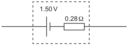
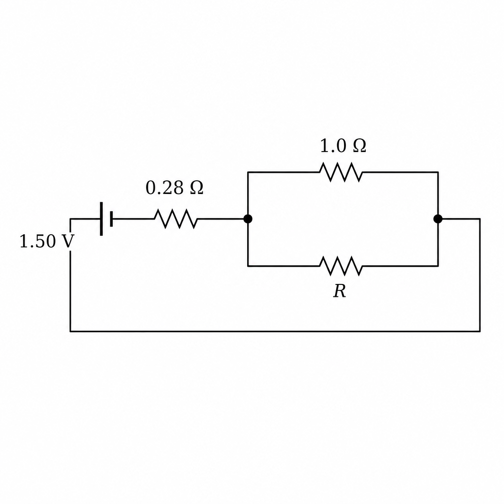
Answer
Two resistors connected in parallel across the cell terminals (one branch , other branch ).
See diagram
Background Concept
Two components are in parallel if they are connected between the same pair of nodes, so they share the same potential difference. In a circuit diagram, this means the branches split from one node and rejoin at the other node.
Understanding the Question
You are asked to modify the circuit so that the two resistors ( and ) are no longer end-to-end (series), but instead each forms its own branch connected directly across the cell terminals.
Approach
Identify the two terminals of the cell (the two nodes provided on Fig. 7.2). Draw two separate branches between these same two nodes: one containing the resistor and one containing the resistor.
Step-by-Step Reasoning
- Keep the given cell symbol and its internal resistance as already drawn.
- Use the two wires provided from the cell terminals as the two nodes for the parallel network.
- Draw two distinct paths between these nodes:
- Branch 1: a resistor labelled .
- Branch 2: a resistor labelled .
- Ensure both branches start and end at the same pair of nodes (this is what makes them parallel).
Key Takeaways
- Parallel components share the same p.d. because they connect across the same two nodes.
- A correct circuit diagram must clearly show a split and rejoin (two branches).
Common Mistakes
- Drawing the resistors still in series (one after the other) rather than in separate branches.
- Connecting one resistor to only one terminal of the cell (an open circuit branch).
Things to Be Careful About
- Both resistors must be connected directly across the cell terminals, not across the internal resistance symbol alone.
- Label both resistor values clearly ( and ).
Explain, without calculation, whether the terminal p.d. across the cell is now less than, equal to or greater than .
Answer
The terminal p.d. is less than .
Putting the resistors in parallel reduces the external resistance, so the current increases. The internal drop increases, so decreases.
Less than 1.36 V
Background Concept
The terminal p.d. of a cell supplying current is
where is internal resistance. For a fixed and , the only way changes is through changes in the current .
Also, the equivalent resistance of two resistors in parallel is smaller than either resistor alone:
So switching from series to parallel reduces the external resistance.
Understanding the Question
Initially (series), the terminal p.d. was . Now the same two resistors are reconnected in parallel. The question asks, without doing any calculations, whether the new terminal p.d. is less than, equal to, or greater than .
Approach
Think in a chain:
- parallel connection (\Rightarrow) smaller external resistance,
- smaller external resistance (\Rightarrow) larger current drawn from the cell,
- larger current (\Rightarrow) larger lost volts inside the cell,
- larger lost volts (\Rightarrow) smaller terminal p.d. .
Step-by-Step Reasoning
- In series, total external resistance is .
- In parallel, the equivalent resistance is less than the smallest branch resistance (so it will be less than ).
- A smaller external resistance means the circuit draws a larger current from the cell.
- Since the internal resistance is unchanged, the internal p.d. drop becomes larger.
- Therefore, using , the terminal p.d. must decrease.
So the terminal p.d. is less than .
Key Takeaways
- Parallel circuits draw more current because their equivalent resistance is smaller.
- With internal resistance present, drawing more current reduces the terminal p.d.
Common Mistakes
- Saying the terminal p.d. becomes equal to the e.m.f. because “the resistors are in parallel” (terminal p.d. only equals e.m.f. when ).
- Thinking that because the resistors are in parallel “the voltage increases”; the cell’s e.m.f. is fixed and internal resistance causes a drop when current increases.
Things to Be Careful About
- The key idea is that internal resistance makes the terminal p.d. depend on current.
- You must mention the link: lower external resistance (\Rightarrow) higher current (\Rightarrow) bigger (\Rightarrow) smaller terminal p.d.; missing the internal resistance argument typically loses credit.