Physics 9702/13 — May/June 2024
Cambridge AS Level · Multiple Choice (AS Level) · answer key with instant marking and worked solutions
Topics Work, Energy and Power · Physical Quantities and Units · Forces, Density and Pressure · Waves · D.C. Circuits · Dynamics · +5 more
Tap an option under each question to check it — your score builds as you go.
What is equal to ?
Options
A
B
C
D
Working
Since ,
Answer
C
C
Background Concept
SI prefixes represent powers of 10. In particular,
So
Converting a small decimal into standard form (scientific notation) makes it easy to identify which prefix applies.
Understanding the Question
We are asked to rewrite
using one of the prefixed units listed in the options (mJ, MJ, \mu J, nJ). So we need the corresponding power of 10.
Approach
- Convert the given value in joules into standard form .
- Recognise which prefix corresponds to that power of 10.
- Choose the option with the same numerical value.
Step-by-Step Reasoning
Rewrite the decimal:
So the energy is:
Now use the definition :
Therefore the correct option is C.
Key Takeaways
- Convert decimals to standard form to spot the power of 10.
- Memorise common prefixes: , , , .
Common Mistakes
- Confusing (micro, ) with m (milli, ).
- Treating as “microjoule” instead of megajoule (it is ).
- Miscounting zeros when converting to standard form.
Things to Be Careful About
- Case matters in prefixes: (mega) is not the same as (milli).
- Check the exponent sign: small numbers correspond to negative powers of 10.
- Ensure the unit stays as joules; only the prefix changes.
The measurement of a physical quantity may be subject to random errors and to systematic errors.
Which statement is correct?
Options
A A systematic error cannot be reduced by adjusting the apparatus.
B A systematic error results in a different reading each time the measurement is taken.
C Random errors are always caused by the person taking the measurement.
D Random errors can be reduced by taking the average of several measurements.
Working
Random errors cause scatter about the true value and can be reduced by repeating measurements and taking the mean.
Answer
D
D
Background Concept
Measurements are affected by two main types of error:
- Random errors cause readings to vary unpredictably above and below the true value due to uncontrollable fluctuations (e.g. reaction time, small environmental changes, limited instrument resolution). They mainly affect precision (the spread of readings).
- Systematic errors shift all readings in the same direction away from the true value (e.g. zero error, miscalibration, parallax due to consistent viewing angle). They mainly affect accuracy (closeness to the true value).
A key idea is how to reduce each type:
- Random errors are reduced by repetition and averaging (the mean tends to be closer to the true value than a single reading).
- Systematic errors are reduced by correcting the cause (e.g. calibrating, zeroing, adjusting the apparatus/procedure).
Understanding the Question
You are given four statements about random and systematic errors. The task is to choose the one statement that correctly describes the nature of these errors or how to reduce them.
Approach
Use the definitions:
- Check whether each statement matches random or systematic behaviour.
- Check whether the proposed method (if any) is actually effective for that type of error.
- Pick the only statement that is fully correct.
Step-by-Step Reasoning
-
A: “A systematic error cannot be reduced by adjusting the apparatus.” This is false. Many systematic errors (e.g. zero error, calibration error) can be reduced/corrected by adjusting or calibrating the apparatus.
-
B: “A systematic error results in a different reading each time…” This describes random error (scatter), not systematic error. So false.
-
C: “Random errors are always caused by the person…” False. Random errors can come from many sources (e.g. electrical noise in sensors, fluctuations in temperature, limited scale resolution), not only the observer.
-
D: “Random errors can be reduced by taking the average of several measurements.” True: averaging repeated readings reduces the effect of random fluctuations and improves precision.
Therefore, the correct option is D.
Key Takeaways
- Random errors → scatter in readings → reduced by repeats and mean.
- Systematic errors → consistent offset → reduced by calibration/zero correction/improving method.
- Precision relates to random error; accuracy relates to systematic error.
Common Mistakes
- Saying averaging reduces systematic error (it does not; the mean would still be shifted).
- Thinking systematic error causes readings to vary each time (that is random error).
- Assuming random errors must be due to “human error” only.
Things to Be Careful About
- A set of repeated readings with a consistent offset suggests a systematic error even if the readings are tightly clustered.
- When you take many readings, the spread decreases in importance for the mean, but any systematic offset remains unless corrected.
- In MCQs like this, look for statements that are true without any extra conditions (e.g. “always” is often a clue to a false statement unless it is genuinely universal).
The Young modulus of the material of a wire is to be found. The Young modulus is given by the equation shown.
The wire is extended by a known force and the following measurements are made.
Which measurement has the largest effect on the uncertainty in the value of the calculated Young modulus?
| measurement | symbol | value |
|---|---|---|
| length of wire before force applied | ||
| diameter of wire | ||
| force applied | ||
| extension of wire with force applied |
Options
A length of wire before force applied
B diameter of wire
C force applied
D extension of wire with force applied
Working
From
so
Percentage uncertainties:
Largest contribution is from .
Answer
B
B
Background Concept
When a quantity is calculated from measured values, its uncertainty depends on (i) how uncertain each measurement is and (ii) how strongly the result depends on that measurement.
For multiplication and division, fractional (or percentage) uncertainties add:
- If , then
For powers, the fractional uncertainty is multiplied by the power:
- If , then
These are the standard A-Level “worst-case” (maximum) rules used for uncertainty propagation.
Understanding the Question
You are given
and the measured values with their absolute uncertainties for , , and .
The question asks: which one measurement contributes the most to the uncertainty in the calculated value of ? So we compare the size of each term in the fractional uncertainty of .
Approach
- Write as a proportionality to see the dependence:
- Use the fractional-uncertainty addition rule for products/quotients.
- Apply the power rule to the term (this doubles the fractional uncertainty from ).
- Calculate the percentage uncertainty for each measurement and identify the largest.
Step-by-Step Reasoning
Start from
Hence the fractional uncertainty is approximately
Now compute each fractional uncertainty:
- For :
- For :
- For , first find then double it because of :
so
- For :
Comparing contributions: , , , . The largest is clearly the diameter contribution, because it is relatively uncertain and also squared in the formula.
Therefore the measurement with the largest effect on the uncertainty in is (option B).
Key Takeaways
- Compare uncertainties using fractional (percentage) uncertainty, not absolute uncertainty.
- For a quantity in the denominator, its fractional uncertainty still adds.
- Powers matter: if is squared, its fractional uncertainty contribution doubles.
- The dominant uncertainty is often from the measurement with the largest percentage uncertainty and/or highest power.
Common Mistakes
- Forgetting the factor of for .
- Comparing absolute uncertainties directly (e.g. vs ) even though the quantities have different sizes and units.
- Thinking quantities in the denominator “subtract” uncertainties (they do not for the standard worst-case method).
Things to Be Careful About
- Use consistent significant figures when comparing percentages; you only need enough precision to see which is largest.
- The units (m vs mm) do not matter for fractional uncertainty as long as numerator and denominator are in the same unit.
- The question asks for the largest effect on uncertainty, so you must compare the fractional contributions, not compute itself.
Two physical quantities combined together as a product can produce a scalar quantity or a vector quantity.
Which product of two quantities produces a scalar quantity?
Options
A (force) (displacement of an object in the direction of the force)
B (mass) (acceleration of the mass)
C (pressure) (area on which the pressure acts)
D (velocity) (time for which an object has that velocity)
Working
Work done:
where is the displacement component in the direction of the force, so is a scalar.
Other products give vectors (e.g. gives force, gives displacement).
Answer
A
A
Background Concept
A scalar has magnitude only (e.g. mass, time, pressure, energy). A vector has both magnitude and direction (e.g. displacement, velocity, acceleration, force).
When multiplying quantities:
- scalar (\times) scalar (\to) scalar
- scalar (\times) vector (\to) vector
- vector (\times) vector is not a simple “multiplication” in physics unless a specific product is defined. The most common relevant one here is the dot product:
This produces a scalar (work done / energy transferred).
Understanding the Question
We are given four products of two physical quantities and asked which product produces a scalar quantity.
So for each option we decide whether the result is scalar or vector, using the scalar/vector nature of each quantity and (where appropriate) known physics definitions.
Approach
Check each option:
- Identify whether each factor is scalar or vector.
- If a factor is a vector, decide whether the product is intended as a scalar multiple (giving a vector) or a dot-product-like combination (giving a scalar).
- Pick the one that must be scalar.
Step-by-Step Reasoning
Option A: (force) (\times) (displacement in the direction of the force)
- Force is a vector (\vec{F}).
- “Displacement in the direction of the force” means the component of displacement along (\vec{F}), i.e. (s\cos\theta), which is a scalar.
- The product is
This is work done, and work/energy is a scalar.
So A produces a scalar.
Option B: (mass) (\times) (acceleration)
- Mass (m) is scalar.
- Acceleration (\vec{a}) is vector.
This gives force, a vector.
Option C: (pressure) (\times) (area)
- Pressure (p) is scalar.
- Area (A) is scalar.
- The product (pA) gives the magnitude of the force on an area in a uniform pressure, but the actual force has a direction (normal to the surface). In vector form you would write (\vec{F} = pA,\hat{n}).
So the physical quantity “force” is vector; (pA) alone is not the full vector.
Option D: (velocity) (\times) (time)
- Velocity (\vec{v}) is vector.
- Time (t) is scalar.
This gives displacement, a vector.
Therefore the only clearly scalar outcome is A.
Key Takeaways
- Work done is a scalar: (W = \vec{F} \cdot \vec{s} = Fs\cos\theta).
- Multiplying a vector by a scalar gives a vector (e.g. (\vec{s} = \vec{v}t), (\vec{F} = m\vec{a})).
- Always check whether the question implies a dot product (scalar) or just a scalar multiple (vector).
Common Mistakes
- Treating (m\times a) as a scalar because (m) is scalar, forgetting that acceleration is a vector so (m\vec{a}) is a vector.
- Thinking (v\times t) is a scalar “distance” rather than the vector displacement (unless speed is stated instead of velocity).
- For pressure (\times) area: giving “scalar” without noting that force is a vector; (pA) is only the magnitude unless a direction is specified.
Things to Be Careful About
- Wording like “in the direction of the force” is a strong clue that a component is being taken and the product is the dot product, giving a scalar.
- Distinguish velocity (vector) from speed (scalar). If the option had said speed (\times) time, that would give a scalar distance.
- In pressure questions, direction is typically perpendicular to the surface; without a direction unit vector (\hat{n}), you have only the magnitude (pA).
The diagram shows a velocity–time graph for an object moving in a straight line.
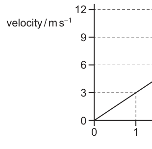
What is the displacement during the last seconds of the motion?
Options
A
B
C
D
Working
From the graph: at , and at , .
Displacement in last (from to ) is area under the graph:
Answer
C
C
Background Concept
For motion in a straight line, a velocity–time graph shows how velocity changes with time .
The key fact is:
- Displacement over a time interval equals the area under the – graph for that interval.
This works because for a small time , the displacement is approximately ; adding (integrating) these contributions gives the total displacement.
Understanding the Question
The graph is a straight line from to , so velocity increases uniformly.
“Last seconds of the motion” means the time interval from:
We must find the area under the graph between these times.
Approach
- Read (or calculate) the velocities at and .
- The region under the straight-line section between and is a trapezium.
- Use trapezium area = average of parallel sides width in time.
Step-by-Step Reasoning
-
Read velocities from the graph:
- At , the dashed line shows .
- At , the end point is .
-
Displacement between and is the trapezium area:
Here , , and :
So the correct option is C.
Key Takeaways
- Displacement over an interval is the area under the velocity–time graph over that interval.
- For a straight-line segment, the area is often easiest as a trapezium.
Common Mistakes
- Finding the area from to (first 2 seconds) instead of the last 2 seconds.
- Using the gradient (acceleration) instead of area (displacement).
- Treating the answer as a velocity and giving units of instead of .
Things to Be Careful About
- Make sure you use the correct time interval: here it is .
- Always include units: area under – has units .
- When using trapezium area, use (not or similar mix-ups).
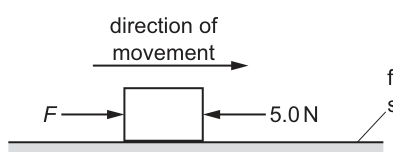
A block is moving along a horizontal frictionless surface. A constant force and a constant resistive force of act on the block as it is moving in the direction of the force , as shown.
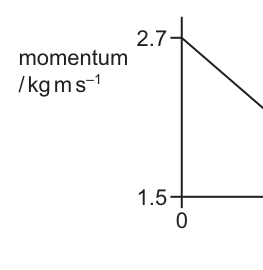
The graph shows the variation with time of the momentum of the block.
What is the magnitude of force ?
Options
A
B
C
D
Working
Gradient of momentum-time graph:
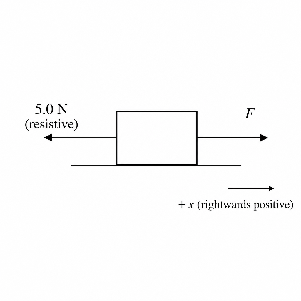
Take rightwards as positive. Then
So
Answer
A
A
Background Concept
Momentum is defined by and is a vector. Newton's second law can be written in momentum form:
So, on a momentum–time graph, the gradient gives the resultant (net) force in the direction chosen as positive. A negative gradient means the net force is opposite to the positive direction.
Understanding the Question
A block moves to the right. There is an applied constant force to the right and a constant resistive force of to the left.
The momentum decreases linearly from at to at . You are asked to find the magnitude of .
Approach
- Use the momentum–time graph to find , which equals .
- Choose rightwards as positive and write the force balance horizontally: .
- Solve for .
Step-by-Step Reasoning
From the graph:
Hence the net force:
The negative sign shows the resultant force is to the left.
Now resolve forces horizontally (right positive):
Substitute :
So the correct option is A.
Key Takeaways
- The gradient of a -vs- graph equals the net force.
- A decreasing momentum (negative gradient) means the net force is opposite the chosen positive direction.
- When multiple forces act, is the algebraic sum using a sign convention.
Common Mistakes
- Using instead of .
- Forgetting the sign of the gradient and treating the net force as .
- Adding the resistive force instead of subtracting it (mixing up directions).
Things to Be Careful About
- Keep a clear positive direction (here, rightwards).
- Remember , so is already in newtons.
- The question asks for the magnitude of (a positive number), but the intermediate can be negative depending on direction.
Newton’s third law describes two forces that are equal in magnitude and form a pair.
Which description of the two forces in such a pair is not correct?
Options
A They act in opposite directions.
B They act on different objects.
C They are the same type of force.
D They cause an object to be in equilibrium.
Working
Newton’s third-law forces are equal in magnitude, opposite in direction, act on different objects, and are the same type of force.
Forces that make an object be in equilibrium must act on the same object and have zero resultant, so a third-law pair cannot by itself make one object be in equilibrium.
Answer
D
D
Background Concept
Newton’s third law states: when two bodies interact, they exert forces on each other that are equal in magnitude and opposite in direction.
Key properties of a Newton’s third-law pair:
- equal magnitude
- opposite direction
- act on two different objects (one force on each object)
- same type of force (e.g. both contact forces, or both gravitational forces)
Equilibrium is different: an object is in equilibrium when the resultant force on that same object is zero (and, for full equilibrium, resultant moment is also zero). The forces that balance for equilibrium all act on the same object.
Understanding the Question
We are given four statements about the forces in a Newton’s third-law pair, and we must choose the one that is not correct.
So we compare each option against the defining properties above.
Approach
- Write down the defining features of a Newton’s third-law pair.
- Check each option:
- if it matches the definition, it is correct;
- if it confuses Newton’s third law with equilibrium (balanced forces on one object), it will be incorrect.
Step-by-Step Reasoning
-
A: “They act in opposite directions.”
This matches Newton’s third law (forces are opposite in direction). So A is correct. -
B: “They act on different objects.”
This is essential: one force acts on one body, the other acts on the other body. So B is correct. -
C: “They are the same type of force.”
Also correct: if one is a frictional/contact/normal/gravitational force, the partner is the corresponding frictional/contact/normal/gravitational force on the other object. -
D: “They cause an object to be in equilibrium.”
This is not correct because the two forces in a Newton’s third-law pair do not act on the same object. Equilibrium requires forces on the same object to sum to zero. A third-law pair therefore cannot directly make one object have zero resultant force.
Hence the incorrect description is D.
Key Takeaways
- Newton’s third-law forces act on different objects; they do not cancel each other on a single object.
- Equilibrium requires balancing forces acting on the same object.
- Action–reaction pairs are equal and opposite and of the same type of force.
Common Mistakes
- Saying the third-law pair “cancels out”: they do not cancel because they act on different objects.
- Treating any equal-and-opposite forces as a third-law pair (they might instead be two different forces on the same object producing equilibrium).
Things to Be Careful About
- Always identify which object each force acts on before deciding if forces form a Newton’s third-law pair.
- For equilibrium questions, focus only on forces acting on the chosen object; do not include the reaction force acting on the other object.
The graph shows the variation with time of the speed of a raindrop falling vertically through air.
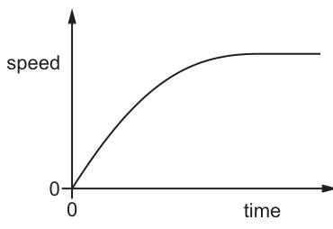
Which statement is correct?
Options
A The acceleration decreases to produce a steady speed.
B The acceleration increases as the speed increases.
C The air resistance decreases as the speed increases.
D The resultant force increases as the speed increases.
Working
The acceleration is the gradient of the speed–time graph.
The graph levels off to a horizontal line, so the gradient decreases to and the speed becomes steady (terminal speed).
Answer
A
A
Background Concept
On a speed–time graph, the acceleration at any instant is the gradient:
For a falling object in air, the forces are weight downward and air resistance (drag) upward. The resultant force is
Newton’s second law links resultant force to acceleration:
Terminal speed occurs when forces balance (), so the resultant force is zero and hence .
Understanding the Question
The graph starts at zero speed, rises quickly, and then gradually becomes horizontal. You are asked which statement correctly describes what is happening as time increases. The key is that the curve becomes horizontal, meaning the speed becomes constant.
Approach
- Use the speed–time graph to deduce how acceleration changes (look at the gradient).
- Connect acceleration to resultant force using .
- Use the idea of terminal speed: constant speed implies zero acceleration and zero resultant force.
Step-by-Step Reasoning
- At the start, the curve is steep, so the gradient is large: acceleration is large.
- As time goes on, the curve becomes less steep: the gradient decreases, so acceleration decreases.
- Eventually the curve is horizontal: gradient , so acceleration .
- Zero acceleration means resultant force is zero (from ).
- Therefore the raindrop reaches a steady (terminal) speed because the acceleration decreases to zero.
So statement A is correct.
(Why the others are wrong, briefly: if acceleration were increasing (B), the curve would get steeper; drag does not decrease with speed (C), it increases; resultant force does not increase with speed (D), it decreases to zero as terminal speed is reached.)
Key Takeaways
- Gradient of a speed–time graph gives acceleration.
- Terminal speed corresponds to zero acceleration and hence zero resultant force.
- In air, increasing speed generally increases drag, reducing the resultant force over time.
Common Mistakes
- Thinking a high speed means a high acceleration: acceleration depends on how quickly speed changes, not the speed itself.
- Saying the resultant force is constant because weight is constant: drag changes with speed, so the resultant changes.
- Confusing “levels off” with “increases more slowly”: in fact it tends to a constant value, so acceleration tends to zero.
Things to Be Careful About
- The graph is speed–time, not distance–time: you must use gradient as acceleration, not speed.
- A horizontal section means , not that forces are absent; it means forces balance.
- For terminal speed, you should state both: constant speed and zero acceleration (and thus zero resultant force).
Which statement about a perfectly elastic collision between two objects is correct?
Options
A Total kinetic energy is conserved and the relative speed of approach equals the relative speed of separation.
B Total kinetic energy is conserved but the relative speed of approach does not equal the relative speed of separation.
C Total kinetic energy is not conserved and the relative speed of approach does not equal the relative speed of separation.
D Total kinetic energy is not conserved but the relative speed of approach does equal the relative speed of separation.
Working
A perfectly elastic collision means kinetic energy is conserved and the coefficient of restitution is , so relative speed of approach equals relative speed of separation.
Answer
A
A
Background Concept
In collisions, two key ideas are often used:
- Conservation of momentum (always true if there is no external resultant impulse):
- Elasticity of the collision, which describes what happens to kinetic energy and to relative speeds.
A perfectly elastic collision is defined by:
- total kinetic energy conserved, and equivalently
- coefficient of restitution
So, for a perfectly elastic collision:
Understanding the Question
You are asked which statement correctly describes a perfectly elastic collision between two objects. The options combine two possible properties:
- whether total kinetic energy is conserved
- whether relative speed of approach equals relative speed of separation
You must choose the one option that matches the definition of a perfectly elastic collision.
Approach
Recall the defining properties of a perfectly elastic collision:
- Kinetic energy is conserved.
- Coefficient of restitution , meaning relative speed of separation equals relative speed of approach.
Then compare these two properties against the four options.
Step-by-Step Reasoning
- For a perfectly elastic collision, by definition, kinetic energy is conserved.
- Also, for a perfectly elastic collision, :
which implies:
- Option A states both of these facts, so it is correct.
Key Takeaways
- Perfectly elastic collision: total kinetic energy conserved.
- Perfectly elastic collision: relative speed of approach = relative speed of separation (because ).
Common Mistakes
- Thinking momentum conservation alone implies kinetic energy conservation (it does not).
- Mixing up elastic and inelastic:
- inelastic: kinetic energy is not conserved and typically relative speeds are not equal.
- perfectly inelastic: objects stick together; kinetic energy is definitely not conserved.
Things to Be Careful About
- The “relative speed” is the speed of one object as seen from the other, i.e. the difference in their velocities along the line of impact.
- Kinetic energy conservation refers to total kinetic energy of the system, not each object separately.
The diagram shows the view from above of a sprinkler system used to water a garden.
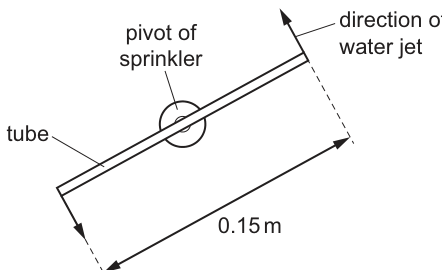
The sprinkler consists of a tube of length . The tube is pivoted in the middle and spins in a horizontal plane as it lets out jets of water from each end. The two water jets are in opposite directions to each other. Each water jet exerts a horizontal force of on the tube at right angles to the tube.
What is the magnitude of the torque on the tube from the water jets?
Options
A
B
C
D
Working
Distance from pivot to each end:
Torque due to one jet:
Total torque (two jets give moments in the same sense):
Answer
C
C
Background Concept
The torque (moment) of a force about a pivot is
where is the force and is the perpendicular distance from the pivot to the line of action of the force.
If two equal forces act in opposite directions at different points (a couple), they produce rotation without a resultant force. The turning effects (torques) of the two forces add, giving a non-zero net torque.
Understanding the Question
A straight tube of total length is pivoted at its midpoint. Each end experiences a horizontal force of magnitude , and each force is at right angles to the tube.
We are asked for the magnitude of the net torque about the pivot due to both forces.
Key information:
- Pivot is at the middle, so each force acts at a distance from the pivot.
- Force is perpendicular to the tube, so the lever arm is simply that half-length.
- The two forces act in opposite directions at opposite ends, which makes a couple; their torques act in the same rotational sense and therefore add.
Approach
- Find the distance from the pivot to one end of the tube.
- Use for one jet (since force is perpendicular).
- Double it because there are two ends producing the same sense of rotation.
- Match the numerical value to the options.
Step-by-Step Reasoning
Distance from pivot to either end:
Torque from one end (perpendicular force, so no sine factor needed):
Now consider both jets. Although the forces are opposite directions, they act on opposite sides of the pivot. This is exactly a couple: each force tends to rotate the tube in the same direction about the pivot, so the torques add:
So the correct option is C.
Key Takeaways
- Use (perpendicular distance to the line of action).
- For a pivot at the midpoint, the lever arm to an end is half the total length.
- Two equal and opposite forces at opposite ends form a couple with non-zero net torque: the moments add.
Common Mistakes
- Using the full length as the lever arm instead of .
- Subtracting the two torques because the forces are opposite, forgetting that they act at different points and produce rotation in the same sense.
- Forgetting that the force is perpendicular and unnecessarily introducing a sine/cosine factor incorrectly.
Things to Be Careful About
- Torque depends on the perpendicular distance from pivot; here that is half the tube length.
- Ensure the final unit is .
- When forces form a couple, the resultant force is zero but the resultant torque is not.
An object is held in equilibrium by three forces. The forces all act in the same plane. The diagram shows two of the forces that act on the object.
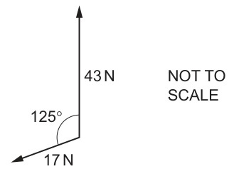
The third force is missing from the diagram.
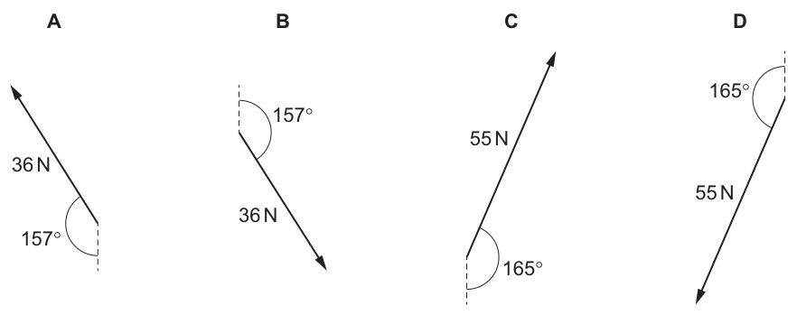
What is the third force?
Options
Working
Take upward as + and right as +.
For the force, angle to upward vertical is :
Resultant of the two shown forces:
Direction of relative to vertical:
So is , to the left of the upward vertical.
Therefore the third force is equal and opposite: down-right (i.e. to the upward vertical).
Answer
B
B
Background Concept
For an object in equilibrium under forces in a plane,
This means the forces add as vectors to form a closed polygon (often a triangle for three forces). Equivalently, if you add any two forces to get a resultant , then the third force must be
i.e. same magnitude as but opposite direction.
A reliable way to add forces is to resolve each force into perpendicular components (e.g. horizontal and vertical ), add the components, then reconstruct the resultant using Pythagoras and trigonometry.
Understanding the Question
Two forces are shown acting from the same point:
- vertically upward.
- downwards and to the left, making an angle of with the upward vertical.
A third force is missing. Since the object is in equilibrium, the third force must exactly cancel the resultant of the two shown forces. The options provide different magnitudes and directions; we must find which matches.
Approach
- Choose axes: up as +, right as +.
- Resolve the force into and components using the given angle to the vertical.
- Add components with the force to get the resultant .
- The third force is (same size, opposite direction). Match that magnitude/direction to the options.
Step-by-Step Reasoning
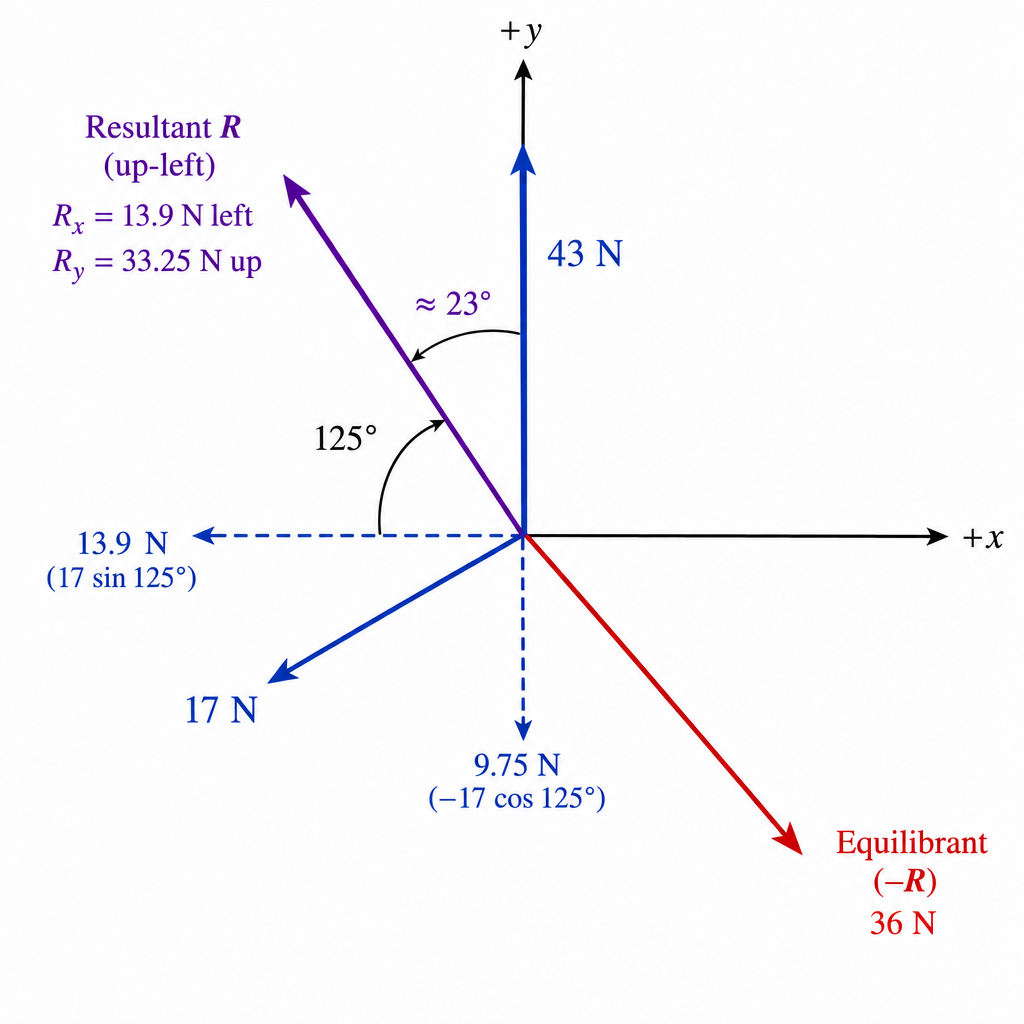
- Resolve the force.
The angle between the force and the upward vertical is . The component along the vertical (upwards positive) is
Since is obtuse, is negative, so this correctly gives a downward vertical component.
Numerically,
The horizontal component has magnitude . The force points to the left, so the -component is negative:
- Add components to get the resultant of the two shown forces.
The force has components and .
So the resultant components are
This means the resultant points up-and-left.
- Magnitude of resultant:
- Direction of resultant relative to the vertical.
Using the right triangle with vertical side and horizontal side ,
So is to the left of the upward vertical.
- Use equilibrium.
The third force must be equal and opposite to , so it must be:
- magnitude
- direction down-and-right, at to the downward vertical.
Many options label the angle to the upward vertical instead; that would be
So the correct option is the force directed down-right with an angle marked : option B.
Key Takeaways
- Equilibrium in a plane means .
- For three forces, the “missing” force is the negative of the resultant of the other two.
- Resolving into components is often the quickest and least ambiguous method.
Common Mistakes
- Using and then treating it as upward (forgetting it is negative for an obtuse angle).
- Taking the angle incorrectly (e.g. using instead of without thinking about the force direction).
- Finding the resultant correctly but forgetting to reverse it for the equilibrant (the third force).
- Mixing up which angle is being quoted in the options (angle to upward vertical vs angle to downward vertical).
Things to Be Careful About
- Always assign signs to components based on direction (left negative , down negative ).
- Check your component results are physically sensible: the force is down-left, so both components should be negative.
- When matching to options, convert between equivalent angle descriptions (e.g. from downward vertical is the same direction as from upward vertical).
The total number of forces acting on an object is two. The object is in equilibrium.
Which statements about the forces are correct?
The two forces must have equal magnitudes.
The two forces must act in the same direction.
The two forces must act through the same point.
Options
A and only
B and only
C and only
D , and
Working
For equilibrium, resultant force is zero, so with only two forces they must be equal in magnitude and opposite in direction.
For equilibrium, resultant moment is also zero, so the two forces must act along the same line of action (often stated as acting through the same point/line), otherwise they form a couple.
So statements and are correct.
Answer
B
B
Background Concept
An object is in equilibrium only if:
- The resultant (net) force is zero: (\sum \vec{F} = 0).
- The resultant moment (torque) about any point is zero: (\sum \tau = 0).
If exactly two forces act on a rigid object, these two conditions strongly restrict how those forces can be arranged:
- (\sum \vec{F} = 0) requires the forces to be equal in magnitude and opposite in direction.
- (\sum \tau = 0) requires the forces to have the same line of action; otherwise they produce a turning effect (a couple).
Understanding the Question
You are told there are only two forces on the object and the object is in equilibrium. You must decide which of the three statements must be true.
The key is that “equilibrium” is not just “no acceleration” (no net force), but also “no tendency to rotate” (no net moment).
Approach
Check each statement against the two equilibrium requirements:
- Use (\sum \vec{F} = 0) to test whether magnitudes/directions are constrained.
- Use (\sum \tau = 0) to test whether their lines of action are constrained.
Then match the true statements to the options A–D.
Step-by-Step Reasoning
- Statement 1: the two forces must have equal magnitudes.
With only two forces, equilibrium means:
So (\vec{F}_2 = -\vec{F}_1), which implies equal magnitudes. Statement 1 is correct.
- Statement 2: the two forces must act in the same direction.
From (\vec{F}_2 = -\vec{F}_1), they must be in opposite directions, not the same direction. If they acted in the same direction, the resultant would be non-zero. Statement 2 is incorrect.
- Statement 3: the two forces must act through the same point.
For a rigid object, it is not enough that forces cancel; they must also not create a couple. If two equal and opposite forces act along different parallel lines, they form a couple and cause rotation.
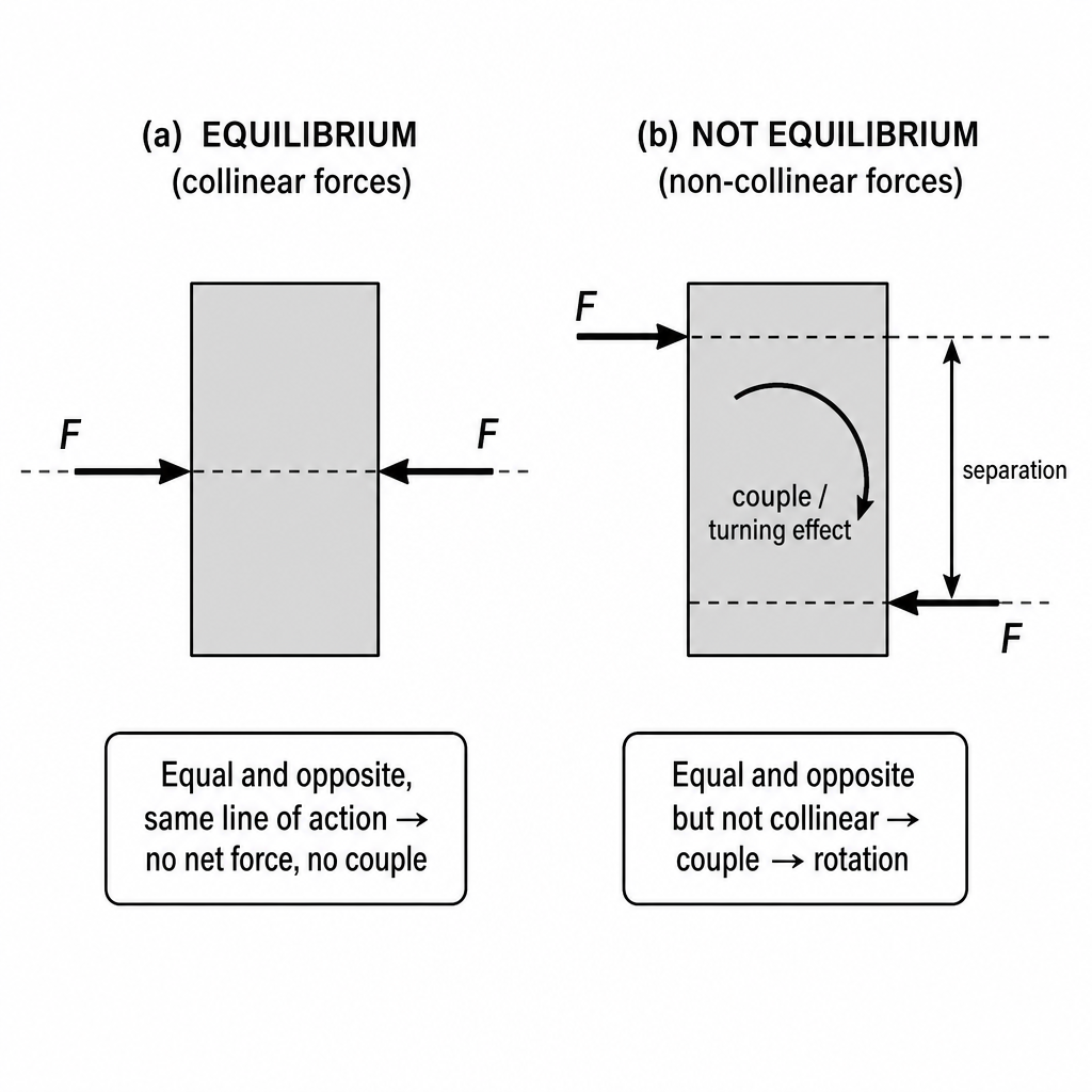
Therefore, for equilibrium with only two forces, they must act along the same line of action (collinear). Many mark schemes express this as “act through the same point/line” (i.e. no separation between their lines of action). Hence statement 3 is taken as correct in this context.
So the correct set is statements 1 and 3 only (\Rightarrow) option B.
Key Takeaways
- Equilibrium requires both (\sum \vec{F}=0) and (\sum \tau = 0).
- With only two forces, equilibrium (\Rightarrow) forces are equal, opposite, and collinear.
- Equal and opposite but not collinear (\Rightarrow) a couple (\Rightarrow) rotation, so not equilibrium.
Common Mistakes
- Thinking equilibrium means only “resultant force is zero” and forgetting the moment condition.
- Concluding “same direction” instead of “opposite direction” when (\sum \vec{F}=0).
- Believing “equal and opposite forces always give equilibrium” (they do not if they form a couple).
Things to Be Careful About
- For an extended object, “same point” is often shorthand for “same line of action” in MCQs; the physical requirement is no turning effect.
- If the question had said “particle” instead of “object”, moments are irrelevant (all forces act at one point), but here it says “object”, so rotation must be considered.
The diagram shows the arrangement of atoms in a particular crystal.
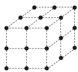
Each atom is at the corner of a cube.
The mass of each atom is . The density of the crystal is .
What is the shortest distance between the centres of two adjacent atoms?
Options
A
B
C
D
Working
Simple cubic: atoms at 8 corners, each shared by 8 cubes → atoms per unit cell .
Mass of unit cell:
Using and :
Shortest distance between adjacent atoms .
Answer
C
C
Background Concept
For a crystal lattice, we often model the solid as made of repeating "unit cells". The density is related to the mass and volume of one unit cell:
For a cubic unit cell with edge length ,
A key idea is that atoms at the corners of a cube are shared between neighbouring cubes. In a simple cubic lattice, each corner atom belongs to 8 different cubes, so each cube effectively contains of each corner atom.
Understanding the Question
You are told:
- atoms are only at the corners of a cube (simple cubic),
- mass of each atom is ,
- density of the crystal is .
The question asks for the shortest distance between the centres of two adjacent atoms. In a simple cubic lattice, the nearest neighbours are along the cube edges, so the shortest centre-to-centre distance is just the cube edge length .
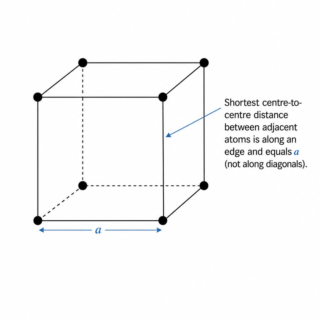
Approach
- Work out how many atoms belong to one unit cell (taking into account sharing of corner atoms).
- Find the unit cell mass .
- Use to find .
- Take the cube root to get , which is the nearest-neighbour distance.
Step-by-Step Reasoning
1) Atoms per unit cell
There are 8 corners. Each corner atom is shared by 8 cubes.
So the number of atoms in one unit cell is
2) Mass per unit cell
3) Use density to find
4) Cube root
This matches option C.
Key Takeaways
- In a simple cubic lattice, effective atoms per unit cell (because ).
- Nearest-neighbour distance in simple cubic is the cube edge length .
- Use to connect microscopic mass to lattice spacing.
Common Mistakes
- Forgetting that corner atoms are shared, and using 8 atoms per unit cell (gives a distance too large).
- Using instead of for the volume of a cube.
- Arithmetic slips when taking the cube root of a number in standard form.
Things to Be Careful About
- The "shortest distance between adjacent atoms" depends on the lattice type; here it is along an edge, not a face diagonal or body diagonal.
- Check units: in and mass in ensures comes out in .
- Cube roots of powers of ten: , so the result should be around (an atomic-scale spacing).
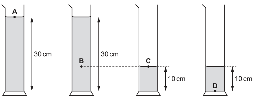
Four measuring cylinders are filled with the same liquid to the heights shown.
At which position is the pressure the greatest?
Options
A
B
C
D
Working
Hydrostatic pressure:
Same liquid so is the same and is constant, so the greatest pressure is at the greatest depth below the liquid surface.
Point is the deepest point below its liquid surface (deeper than ).
Answer
B
B
Background Concept
In a stationary liquid, pressure increases with depth because the liquid lower down must support the weight of the liquid above it. The hydrostatic pressure at depth below the free surface is
where:
- is the (gauge) pressure due to the liquid column,
- is the density of the liquid,
- is gravitational field strength,
- is the vertical depth below the liquid surface.
Key idea: for the same liquid and same , pressure depends only on depth , not on the container shape or total volume.
Understanding the Question
You are shown four measuring cylinders containing the same liquid, but with two different liquid heights ( and ). Points , , , and are at different positions in the liquids.
The question asks which point has the greatest pressure. Since all cylinders are open to the atmosphere, the one at greatest depth below its own liquid surface has greatest pressure.
Approach
- Use .
- Since and are the same for all, compare the depth for each point.
- Choose the point with the largest .
Step-by-Step Reasoning
- Point is near the top surface of a column, so its depth is small.
- Point is at the surface of a column, so (pressure due to liquid is zero there).
- Point is near the bottom of a column, so .
- Point is well below the surface in a column. From the diagram description, is about level with the surface of the column, i.e. about above the base, so its depth below the surface is roughly
This is greater than the depth at (about ), so has the greatest pressure.
Key Takeaways
- In a liquid at rest, pressure increases with vertical depth: .
- For the same liquid, comparing pressures is the same as comparing depths below the surface.
- Container shape does not affect hydrostatic pressure at a given depth.
Common Mistakes
- Choosing the cylinder with the greatest total height without checking the point’s depth below the surface.
- Thinking pressure depends on the amount/volume of water rather than depth.
- Comparing heights above the base instead of depths below the surface.
Things to Be Careful About
- is measured from the liquid surface down to the point, not from the base up.
- Points at the surface have so no hydrostatic (gauge) pressure.
- If the question expects absolute pressure, it would be ; however, the ranking is unchanged because is the same for all points.
In many filament lamps, as much as of energy is emitted as thermal energy for every of energy emitted as light.
What is the efficiency of a filament lamp, as the percentage of electrical energy converted to light energy?
Options
A
B
C
D
Working
Total electrical energy input
Efficiency
Answer
A
A
Background Concept
Efficiency is the fraction of the input energy (or power) that is converted into the desired (useful) form.
To express efficiency as a percentage:
In a filament lamp, the useful output is light energy; thermal energy is wasted from the point of view of producing light.
Understanding the Question
For every emitted as light, the lamp emits as thermal energy. These two outputs together account for the electrical energy supplied (assuming other losses are negligible), so:
- Useful output:
- Wasted output:
- Total input:
The question asks for the percentage of electrical energy converted to light.
Approach
- Add the light and thermal energies to get the total electrical energy input.
- Use .
- Multiply by to get a percentage.
- Match the result to the given options.
Step-by-Step Reasoning
Total energy supplied to the lamp is the sum of the energies it outputs as light and as heat:
Efficiency (useful fraction) is:
Convert to a percentage:
So the correct option is A.
Key Takeaways
- Useful energy for a lamp (in this context) is the light energy, not the heat.
- Total input energy equals the sum of all output energy forms.
- Efficiency is a ratio; percentage efficiency is the ratio multiplied by .
Common Mistakes
- Using as the input energy instead of adding .
- Calculating (wasted fraction) instead of (useful fraction).
- Forgetting to multiply by when asked for a percentage.
Things to Be Careful About
- The wording “for every of light” indicates a ratio; you must form the corresponding total ().
- Efficiency must always be based on useful output divided by total input (not total output of one type).
What is a unit of power?
Options
A
B
C
D
Working
Power is energy transferred per unit time:
So the unit is
Answer
D
D
Background Concept
Power is the rate at which energy is transferred (or work is done). By definition,
So the SI unit of power must be “joules per second”, which is also called the watt ().
Understanding the Question
You are given four possible compound units and asked which one is a unit of power. Since power is energy per unit time, you should look for a unit of the form divided by .
Approach
- Write down the defining equation for power: .
- Convert that directly into units by replacing with joules () and with seconds ().
- Choose the option that matches .
Step-by-Step Reasoning
Start with the definition:
- (work done / energy transferred) has unit joule, .
- has unit second, .
Therefore the unit of is
This corresponds to option D.
Key Takeaways
- Power is a rate: energy per time.
- Unit of power: , which is the watt ().
Common Mistakes
- Confusing power with energy: choosing instead of .
- Mixing up other derived quantities: e.g. is volt (), not power.
Things to Be Careful About
- Look for “per second” () when the quantity is a rate.
- Remember that many compound units have special names (e.g. is ), but you should always be able to get the unit from the defining equation.
An object is in a uniform gravitational field. The graph shows how the change in gravitational potential energy of the object varies with the vertical distance moved by the object from a fixed point.
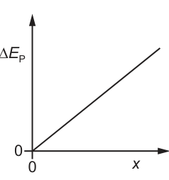
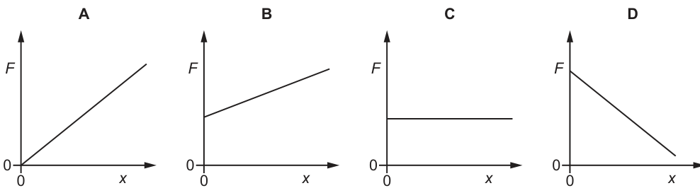
Which graph shows how the gravitational force acting on the object varies with distance ?
Options
Working
In a uniform gravitational field,
So
The – graph is a straight line through the origin with constant gradient, so is constant (independent of ).
Answer
C
C
Background Concept
In a uniform gravitational field, the gravitational force (weight) on an object is constant:
If the object is moved vertically through a distance (upwards), the increase in gravitational potential energy equals the work done against the gravitational force:
More generally, if energy varies with position, the force magnitude in the direction of motion is the rate of change of potential energy with distance:
Understanding the Question
You are given a graph of against vertical distance . It is a straight line through the origin with constant positive gradient. The question asks which vs graph matches this situation.
Approach
Use the relationship between potential energy and force:
- From the graph, determine how depends on .
- Use (or equivalently the gradient idea ).
- Translate “constant ” into the correct – graph shape.
Step-by-Step Reasoning
- The given vs graph is a straight line through the origin, so
- Using
rearrange to get
-
Since is the gradient of the straight line (a constant), is constant and does not change with .
-
A constant positive force corresponds to a horizontal line above zero on an vs graph.
Therefore the correct option is C.
Key Takeaways
- In a uniform gravitational field, is constant.
- A straight-line – graph implies constant force because .
- Constant force means a horizontal line on an – graph.
Common Mistakes
- Choosing a graph where increases with (confusing energy increasing with force increasing).
- Forgetting that the force is given by the gradient of the energy–distance graph.
- Mixing up sign and magnitude: the gravitational force acts downward, but the options here show the magnitude of .
Things to Be Careful About
- The graph shows increasing with ; that indicates constant positive gradient, not a changing gradient.
- For multiple-choice graphs, focus on the shape (constant vs changing), not on exact numerical values.
- If direction were required, you would need a sign convention (upward positive would give gravitational force negative), but these options present as positive values.
A block of mass is released from rest on a slope. It travels down the slope and falls a vertical distance of . The block experiences a frictional force parallel to the slope of .
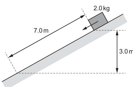
What is the speed of the block after falling this distance?
Options
A
B
C
D
Working
Loss of GPE:
Work done against friction:
Gain in KE:
Answer
A
A
Background Concept
As an object moves down a slope and loses height, its gravitational potential energy (GPE) decreases by
If there are no energy losses, this lost GPE becomes kinetic energy (KE):
When a frictional force acts, mechanical energy is not conserved: friction does negative work on the moving object, removing energy from the mechanical store. For a constant friction force acting over a distance along the direction of motion, the energy dissipated is the work done against friction:
Then the energy balance becomes
Understanding the Question
The block starts from rest, slides down the slope, and drops vertically by . You are asked for its speed after this motion.
Key given values:
- vertical drop (this sets the GPE loss)
- distance along slope (this sets the work done against friction)
- friction force (up the slope)
- initial speed
Approach
- Compute the loss of GPE using (only the vertical drop matters).
- Compute the work done against friction using (force is parallel to slope and constant).
- Subtract the friction loss from the GPE loss to get the KE gained.
- Use to find .
- Match the result to the closest option.
Step-by-Step Reasoning
- Loss of gravitational potential energy:
- Energy dissipated by friction (work done against friction):
- The remainder becomes kinetic energy:
- Convert KE to speed:
With ,
So the correct option is A.
Key Takeaways
- Use for the energy available from a vertical drop (independent of path).
- Friction removes energy equal to where is the distance moved along the surface.
- Final kinetic energy is the energy available minus energy lost to non-conservative forces.
Common Mistakes
- Using as the height in (height is ).
- Using for the friction work distance (friction acts along the slope, so use ).
- Forgetting to subtract the friction work (or adding it).
- Forgetting the square root when solving from .
Things to Be Careful About
- Check which distance belongs in each formula: vertical drop for GPE, along-slope distance for friction work.
- Keep units consistent: J for energies, N and m for work.
- Significant figures: given data are mostly 2 s.f., so is appropriate.
Two wires, one made of brass and the other of steel, are stretched in an experiment. Both wires obey Hooke’s law during this experiment.
The Young modulus for brass is less than the Young modulus for steel.
Which graph shows how the stress varies with strain for both wires in this experiment?
Options
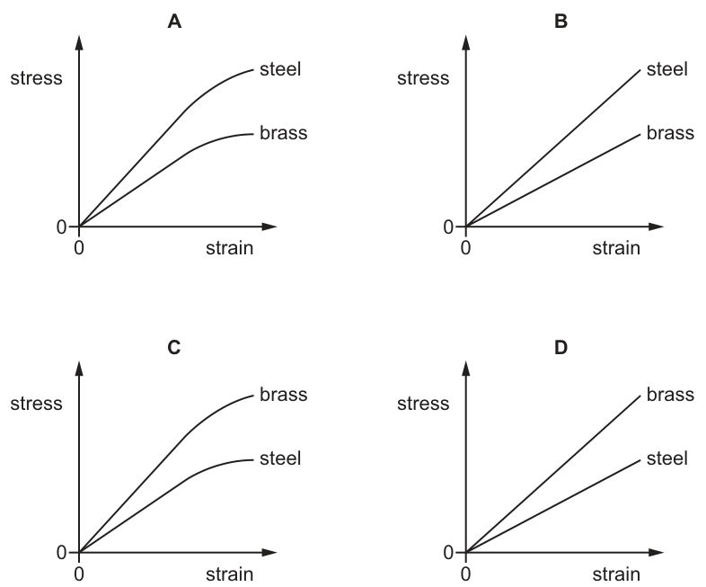
Working
Hooke’s law ⇒ stress ∝ strain, so stress–strain graph is a straight line through the origin.
Young modulus ⇒ gradient of stress–strain graph.
Brass has smaller than steel ⇒ brass line has smaller gradient (less steep) than steel line.
Answer
B
B
Background Concept
For a material obeying Hooke’s law, stress is proportional to strain:
where:
- stress (unit: ),
- strain (no unit),
- is the Young modulus (unit: ).
This equation has the same form as , so a stress–strain graph is a straight line through the origin, and the gradient is .
Understanding the Question
You are told:
- both wires (brass and steel) obey Hooke’s law throughout the experiment,
- .
You must choose the graph that correctly shows stress varying with strain for both materials.
Approach
- Use “obeys Hooke’s law” to decide the shape of each graph (linear, through origin).
- Use to link Young modulus to the gradient.
- Since steel has the larger , the steel line must be steeper than the brass line.
Step-by-Step Reasoning
- Under Hooke’s law:
So when strain is zero, stress is zero → line passes through the origin.
- Rearranging for gradient:
On a graph of stress (y-axis) against strain (x-axis), the gradient is .
- Given :
- brass must have the smaller gradient,
- steel must have the larger gradient.
Therefore, the correct option is the one with two straight lines through the origin, with the steel line steeper than the brass line: option B.
Key Takeaways
- If a material obeys Hooke’s law, its stress–strain graph is a straight line through the origin.
- The Young modulus equals the gradient of the stress–strain graph.
- A larger Young modulus means a steeper stress–strain line.
Common Mistakes
- Choosing a curved graph: curvature suggests the material is no longer obeying Hooke’s law.
- Thinking the higher line must be the lower Young modulus: at the same strain, higher stress means larger , not smaller.
- Mixing up axes: the question is stress (vertical) against strain (horizontal), so gradient is .
Things to Be Careful About
- “Both wires obey Hooke’s law during this experiment” means you must not include any non-linear (plastic) region.
- Young modulus comparisons are comparisons of gradient, not of where the lines cross the axes (they should both pass through the origin here).
A sample of material is stretched by a tensile force to a point beyond its elastic limit. The tensile force is then reduced to zero. The force–extension graph is shown.
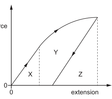
Which area represents the net work done on the sample?
Options
A
B
C
D
Working
Work done on loading = area under loading curve .
Work done on sample during unloading is negative, with magnitude equal to area under unloading line .
Net work done on sample:
Answer
B
B
Background Concept
For a force that changes with extension , the work done by the force is
On a force–extension graph, this integral is represented by the area under the curve.
- Loading (stretching): increases, so the external force does positive work on the sample (energy is transferred into elastic strain energy and, beyond the elastic limit, into internal energy associated with plastic deformation).
- Unloading: decreases. The force is still tensile but the displacement is opposite, so the work done on the sample is negative. Equivalently, the sample does positive work on the surroundings as it contracts.
Therefore,
Understanding the Question
The sample is stretched beyond its elastic limit and then the force is reduced to zero, leaving a permanent extension.
The graph labels three regions:
- : area under the initial straight (Hooke’s law) part of the loading curve.
- : area between the loading curve and the unloading straight line.
- : triangular area under the unloading line down to the extension axis.
The question asks which labelled area corresponds to the net work done on the sample over the whole process (load then unload to zero force).
Approach
- Treat the area under the loading curve as the total work done on the sample while stretching.
- Treat the area under the unloading line as the work returned by the sample (so subtract it to get net work done on the sample).
- Express these areas in terms of , , and , then simplify.
Step-by-Step Reasoning
- Work done during loading (stretching from zero extension to the maximum extension) is the full area under the loading curve.
From the way the regions are labelled, that total area is made up of:
- (under the initial linear section), plus
- the rest of the area under the loading curve, which is split into (between loading and unloading) and (the part that lies under the unloading line).
So,
- Work returned during unloading equals the area under the unloading line. This is the triangular region .
So the magnitude of energy returned is , meaning the work done on the sample during unloading is .
- Net work done on the sample:
Hence the correct option is .
Key Takeaways
- Area under an vs extension graph gives the work done (energy transferred).
- Net work over loading and unloading is the difference between the two areas.
- The area between loading and unloading curves represents energy dissipated (e.g. internal heating), but here there is also additional net work due to permanent extension.
Common Mistakes
- Taking the net work to be just the loop area (that would correspond to a complete cycle returning to the original extension).
- Forgetting that unloading corresponds to negative work done on the sample.
- Assuming the unloading line must return to the origin (it does not once the elastic limit has been exceeded).
Things to Be Careful About
- The sample is not returned to zero extension; it is returned to zero force, leaving a permanent extension. That changes what counts as “net” work.
- Always interpret areas with the correct physical meaning: loading area is energy put in; unloading area is energy given back.
A wire is fixed at one end and is extended by a force acting on the other end. This causes the wire to have an elastic potential energy of .
The force applied to the wire is now changed to a force . This causes the wire to have a new elastic potential energy of .
The wire obeys Hooke’s law.
What is the relationship between and ?
Options
A
B
C
D
Working
For a Hooke’s law wire, .
Elastic potential energy:
Substitute :
So .
Answer
C
C
Background Concept
A wire (or spring) that obeys Hooke’s law has force proportional to extension:
where is the spring constant (stiffness) and is the extension.
The elastic potential energy stored is the work done in stretching it. Because the force increases linearly from to as the extension increases from to , the work done is the area under the – graph (a triangle):
Using , you can also write energy in terms of force:
So, for the same wire (constant ), elastic energy is proportional to .
Understanding the Question
Two different forces and are applied to the same Hooke’s-law wire.
- When the force is , the elastic energy is .
- When the force is , the elastic energy is .
You are asked which relationship between and matches these energies.
Approach
Use the Hooke’s-law energy relationship to connect energy with force. Since the wire is the same in both cases, is unchanged, so compare the ratio and convert that into a ratio of forces using the square relationship.
Step-by-Step Reasoning
From Hooke’s law, .
Elastic energy stored:
Replace using :
Thus, for a fixed :
So the ratio of energies is the square of the ratio of forces:
Substitute values:
Take the square root:
So:
This corresponds to option C.
Key Takeaways
- For Hooke’s-law behaviour, .
- Elastic potential energy is the area under the – graph: .
- For the same spring/wire, (or ).
- When energy increases by a factor of , force increases by a factor of .
Common Mistakes
- Assuming instead of (forgetting the force increases with extension).
- Using (that would only apply if the force were constant during the stretch).
- Forgetting to take the square root when converting an energy ratio into a force ratio.
Things to Be Careful About
- The wire must be in the Hooke’s-law region (stated), so is constant and the proportional reasoning is valid.
- Always check whether the relationship is linear or squared: energy in Hooke’s law depends on and therefore on .
The diagram shows a representation of a wave on the screen of an oscilloscope.
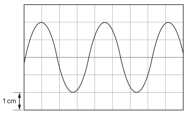
The y-gain is set to .
What is the amplitude of the wave?
Options
A
B
C
D
Working
Amplitude on screen
Answer
C
C
Background Concept
For a wave, the amplitude is the maximum displacement from the equilibrium (centre) position to a crest (or to a trough). On an oscilloscope display, the vertical axis represents voltage, and the setting called y-gain (or volts-per-division) tells you how much voltage corresponds to a given vertical distance on the screen.
If the y-gain is , then a vertical height of on the screen represents a voltage of .
Understanding the Question
You are shown a sinusoidal trace on an oscilloscope grid. The trace oscillates about the central horizontal line (the equilibrium line).
You are told:
- y-gain ,
- each grid square corresponds to ,
- the crest is about two vertical divisions above the centre line (and the trough is two divisions below).
The question asks for the amplitude (centre to crest), not the peak-to-peak value (crest to trough).

Approach
- Read the amplitude in cm directly from the grid: count divisions from the centre line to a crest.
- Convert that screen amplitude to a voltage using:
Step-by-Step Reasoning
- From the diagram, the crest is squares above the centre line.
- Since square , the screen amplitude is:
- Convert to voltage amplitude using the y-gain:
- Match to the options: corresponds to option C.
Key Takeaways
- Amplitude is measured from the centre line to a crest (or trough), not crest-to-trough.
- Oscilloscope y-gain converts vertical distance on screen to voltage.
- Use: .
Common Mistakes
- Using peak-to-peak height ( here) and giving (option D) instead of the amplitude.
- Measuring from crest to the centre but miscounting divisions (e.g. counting small squares inconsistently).
- Forgetting the units conversion is already built into , so no extra factors are needed.
Things to Be Careful About
- Always identify the equilibrium line first (the central horizontal axis of oscillation).
- Ensure you use the correct scale: here division is explicitly .
- Quote the amplitude in the same voltage unit as the y-gain (mV here).
A transverse progressive wave on a string has a wavelength of and an amplitude of .
The speed of the wave on the string is .
What is the distance travelled by a point on the string in a time of ?
Options
A
B
C
D
Working
In , number of cycles:
Distance travelled in one complete oscillation :
Total distance travelled:
Answer
C
C
Background Concept
In a transverse progressive wave on a string, the wave pattern travels along the string, but each point (particle of the string) oscillates up and down about its equilibrium position.
Key relations:
- Wave equation:
where is wave speed, is frequency, and is wavelength.
- Amplitude is the maximum displacement of a point from equilibrium.
For one complete oscillation (one period), a point moves from equilibrium to +, back through equilibrium to (-A), and back to equilibrium. The total distance travelled in one cycle is therefore:
(Note this is distance, not displacement.)
Understanding the Question
You are given:
- time
You must find the distance travelled by a point on the string in . That means how far the point moves up and down in total, not how far the wave travels along the string.
Approach
- Use to find the frequency .
- Find how many oscillations occur in using .
- Use amplitude to get the distance moved in one full oscillation ().
- Multiply: total distance .
Step-by-Step Reasoning
- Find the frequency:
So the point oscillates 4 times each second.
- Number of oscillations in :
- Distance moved in one complete oscillation:
- From equilibrium to crest:
- Crest back to equilibrium:
- Equilibrium to trough:
- Trough back to equilibrium:
So:
- Total distance in 8 cycles:
This corresponds to option C.
Key Takeaways
- A point on the string oscillates; it does not travel with the wave.
- Use to connect wave speed, wavelength, and frequency.
- Total distance moved by an oscillating point depends on amplitude and number of cycles; one cycle corresponds to a distance .
Common Mistakes
- Calculating and choosing : that is the distance the wave pattern travels along the string, not the distance moved by one point.
- Using instead of for one cycle (that would only count from crest to trough, missing the return parts).
- Confusing distance with displacement: after a whole number of cycles the displacement is zero, but the distance travelled is not.
Things to Be Careful About
- The units cancel correctly in even if you keep cm and s; no need to convert to metres here.
- Ensure you interpret “point on the string” as particle motion (transverse oscillation).
- The calculation assumes whole cycles; here is exactly an integer, making it straightforward.
An ambulance siren emits a sound with a single frequency .
The ambulance travels towards, passes close to, and then travels away from a stationary observer.
Which statement describes the frequency of the sound detected by the observer as the ambulance passes the observer?
Options
A equal to and decreasing
B equal to and increasing
C greater than and constant
D less than and constant
Working
At the instant the ambulance is closest to the observer, its velocity component along the line joining it to the observer is zero, so there is no Doppler shift and the detected frequency is .
Immediately after passing, the ambulance is moving away, so the detected frequency becomes less than and continues to decrease as it travels further away.
Answer
A
A
Background Concept
For a stationary observer and a moving sound source, the Doppler effect occurs because successive wavefronts are emitted from different positions of the source.
- When the source moves towards the observer, wavefronts are closer together (shorter wavelength), so the detected frequency is greater than the emitted frequency.
- When the source moves away, wavefronts are further apart (longer wavelength), so the detected frequency is less than the emitted frequency.
A key idea is that the Doppler shift depends on the radial (line-of-sight) component of the source velocity relative to the observer. If that component is zero, there is no Doppler shift.
Understanding the Question
An ambulance emits sound of single frequency (the frequency in the source frame). A stationary observer hears the siren as the ambulance approaches, passes close by, and then recedes.
The question asks what happens to the detected frequency as the ambulance passes the observer (i.e. at the moment of closest approach and just after).
Approach
- Identify the instant of passing as the moment of closest approach.
- Determine the line-of-sight component of the ambulance velocity at that instant.
- Use the Doppler-effect rule (approaching → higher, receding → lower) to state how the frequency changes just after passing.
Step-by-Step Reasoning
- As the ambulance approaches, its motion has a component towards the observer, so the detected frequency is greater than .
- At the instant it is closest to the observer (the “passes the observer” moment), the ambulance’s velocity is momentarily perpendicular to the line joining it to the observer, so the radial component is zero.
- With zero radial component, there is no compression or stretching of wavefront spacing along the observer line.
- Therefore the detected frequency at that instant is equal to .
- Immediately after passing, the ambulance now has a radial component away from the observer.
- The detected frequency becomes less than .
- As it continues to travel away, the separation increases and the detected frequency continues in the decreasing trend.
So the best matching option is “equal to and decreasing”.
Key Takeaways
- Doppler shift depends on whether the source is approaching or receding along the line of sight.
- At closest approach, the line-of-sight component of velocity can be zero, giving no Doppler shift at that instant.
- Right after passing, the source is receding, so the detected frequency is lower and decreases as distance increases.
Common Mistakes
- Thinking the frequency is constant and greater than while approaching (it changes as geometry changes and then jumps at passing).
- Forgetting the Doppler effect depends on the radial component of velocity, not just “the ambulance is moving”.
- Saying the frequency is still greater than exactly at the passing point; at closest approach the radial component is zero.
Things to Be Careful About
- The observed frequency typically changes abruptly from “higher than ” (just before passing) to “lower than ” (just after passing). The options do not mention the jump explicitly, but they do capture the key fact that at the instant of passing it is , and after that it decreases.
- Interpret “passes the observer” as the moment of closest approach, not some extended time interval.
An electromagnetic wave has a wavelength of in a vacuum.
To which region of the electromagnetic spectrum does this wave belong?
Options
A radio wave
B microwave
C visible light
D X-ray
Working
.
X-rays have wavelengths of order to (about to ), so is an X-ray.
Answer
D
D
Background Concept
Electromagnetic (EM) waves are classified into regions of the electromagnetic spectrum according to their wavelength (\lambda) (or equivalently their frequency (f), since (c = f\lambda) in a vacuum).
Typical wavelength ranges you should know approximately are:
- radio waves: very long, (\gtrsim 10^{-1}\ \text{m}) (and much larger)
- microwaves: roughly (10^{-3}) to (10^{-1}\ \text{m})
- visible light: roughly (4 \times 10^{-7}) to (7 \times 10^{-7}\ \text{m})
- X-rays: roughly (10^{-11}) to (10^{-8}\ \text{m}) (i.e. (0.01) to (10\ \text{nm}))
So once you convert the given wavelength into metres (or nanometres), you can match it to the correct region.
Understanding the Question
You are told an EM wave has wavelength (\lambda = 138\ \text{pm}) in vacuum, and you must identify which region (radio, microwave, visible, X-ray) corresponds to that wavelength.
The key step is converting picometres (pm) into metres or nanometres so you can compare with standard spectrum ranges.
Approach
- Convert (138\ \text{pm}) into metres (or nanometres).
- Compare the result with the typical wavelength ranges for the listed regions.
- Choose the option that contains that wavelength.
Step-by-Step Reasoning
Convert units:
- (1\ \text{pm} = 10^{-12}\ \text{m}).
So,
It is often convenient to express very small wavelengths in nanometres:
- (1\ \text{nm} = 10^{-9}\ \text{m}).
Now compare:
- Visible light is hundreds of nm (about 400–700 nm), so (0.138\ \text{nm}) is far too small.
- X-rays are typically (0.01) to (10\ \text{nm}), so (0.138\ \text{nm}) lies in the X-ray range.
Therefore the correct option is X-ray.
Key Takeaways
- Always convert prefixes correctly: (\text{pico} = 10^{-12}).
- Identify EM spectrum regions by order of magnitude of wavelength.
- X-rays correspond to very short wavelengths, typically fractions of a nanometre to a few nanometres.
Common Mistakes
- Treating (\text{pm}) as (10^{-9}\ \text{m}) (confusing pico with nano).
- Assuming “short wavelength” automatically means visible (visible is not that short in absolute terms: hundreds of nm).
- Not converting units and trying to compare (138\ \text{pm}) directly with (400)–(700\ \text{nm}) without making them consistent.
Things to Be Careful About
- Prefixes: (\text{pm} = 10^{-12}\ \text{m}), (\text{nm} = 10^{-9}\ \text{m}).
- Keep powers of ten accurate: a slip by (10^3) moves you to a different region.
- Use approximate wavelength bands (order-of-magnitude reasoning is usually enough for MCQs).
A student investigates the polarisation of microwaves. The microwaves from the transmitter are vertically polarised. A metal grille acts as a polarising filter when placed between the microwave transmitter and the receiver. The reading on the voltmeter is proportional to the intensity of microwaves transmitted through the grille.
When the transmission axis of the grille is vertical, the voltmeter reads .
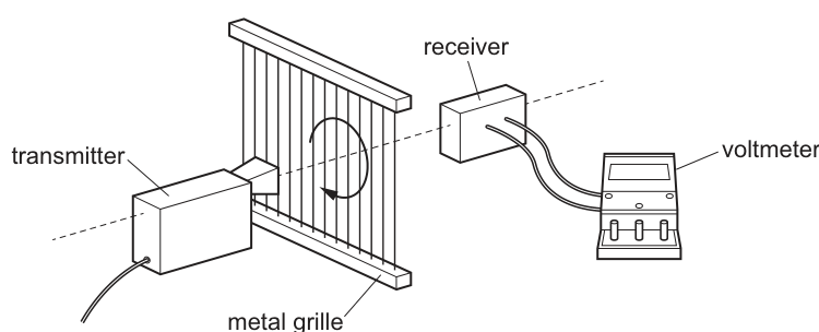
The grille is then rotated through an angle . The voltmeter now reads .
What is ?
Options
A
B
C
D
Working
Voltmeter reading .
With transmission axis vertical: .
After rotation by :
So
Answer
A
A
Background Concept
For linearly polarised waves passing through a polarising filter, the transmitted intensity depends on the angle between the wave’s polarisation direction and the filter’s transmission axis.
Malus’s law states:
where:
- is the maximum transmitted intensity (when axes are aligned),
- is the transmitted intensity at angle ,
- is the angle between the incident polarisation direction and the transmission axis.
Understanding the Question
The microwaves are initially vertically polarised. When the grille’s transmission axis is vertical (aligned), the voltmeter reads , which corresponds to maximum intensity .
After rotating the grille by angle , the voltmeter reads , corresponding to a smaller intensity .
We are told the voltmeter reading is proportional to intensity, so we can use the voltage ratio as an intensity ratio.
Approach
- Treat as proportional to and as proportional to .
- Use Malus’s law in ratio form to eliminate the unknown proportionality constant.
- Solve for .
Step-by-Step Reasoning
Because :
Malus’s law gives:
So:
Take the square root (taking the positive root since for a rotation angle here):
Now find :
This matches option .
Key Takeaways
- Malus’s law: .
- If a measured quantity is proportional to intensity, you can use ratios directly.
- Remember to square root before applying .
Common Mistakes
- Using instead of .
- Doing without taking the square root.
- Swapping the ratio (using ), which would give an impossible .
Things to Be Careful About
- The angle in Malus’s law is between the transmission axis and the incident polarisation direction (here, vertical).
- Ensure the calculator is in degree mode.
- Taking the correct root: for typical polariser rotations in this context, is between and , so use the positive square root.
Two waves superpose. A resultant wave pattern is formed.
Which statement about the two waves must be correct?
Options
A They have the same amplitude.
B They are of the same type.
C They are transverse waves.
D They travel in opposite directions.
Working
For superposition, the displacements add at each point, so the waves must be of the same type (produce the same kind of displacement of the same medium/component).
Answer
B
B
Background Concept
The principle of superposition states that when two or more waves overlap, the resultant displacement at any point is the vector/algebraic sum of the individual displacements at that point.
For this to make physical sense, the displacements being added must be the same physical quantity:
- e.g. two transverse waves on a string both give vertical displacement of the string,
- two sound waves both give pressure/density variations in air.
So a necessary condition is that the waves are of the same type (same nature of oscillation / same medium and component of displacement).
Understanding the Question
We are told that two waves overlap and form a resultant wave pattern. The question asks which statement about the two original waves must be true.
Approach
Check each option and decide whether it is:
- a necessary condition for superposition, or
- merely sometimes true.
Only the necessary condition can be correct.
Step-by-Step Reasoning
- A: same amplitude — not required. Waves with different amplitudes still add to form a resultant displacement.
- B: same type — required. You can only add displacements meaningfully if both waves describe the same kind of displacement (e.g. both are sound pressure variations, or both are transverse displacements of a string).
- C: transverse waves — not required. Superposition applies to transverse and longitudinal waves.
- D: opposite directions — not required. Waves can superpose while travelling in the same direction (interference) or in opposite directions (can form stationary waves), but opposite directions is not a must.
Therefore the only statement that must be correct is B.
Key Takeaways
- Superposition means resultant displacement = sum of individual displacements.
- A necessary condition is that the waves are the same type (same physical displacement quantity).
- Same amplitude, being transverse, or travelling in opposite directions are not required.
Common Mistakes
- Thinking superposition only happens for stationary waves, so choosing “opposite directions”.
- Assuming interference requires equal amplitudes.
- Assuming superposition is only for transverse waves.
Things to Be Careful About
- “Same type” means the waves must be able to produce and add the same kind of displacement at a point (same medium/component), not necessarily the same amplitude or direction.
- Many superposition situations involve waves travelling in opposite directions, but that is a special case, not the defining condition.
A water wave passes through a gap in a harbour wall and diffracts. The gap has a width of .
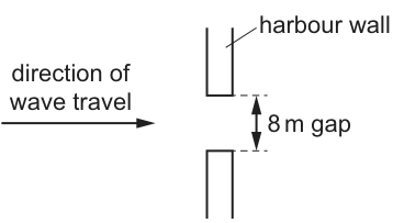
The wave travels directly towards the gap.
For which wavelength is the diffraction of the wave greatest?
Options
A
B
C
D
Working
Diffraction is greatest when the wavelength is comparable to the gap width .
Here , so choose .
Answer
D
D
Background Concept
Diffraction is the spreading out of a wave after it passes through a gap (aperture) or around an obstacle. The amount of spreading depends mainly on the ratio
where:
- is the wavelength of the wave,
- is the width of the gap.
Key idea:
- If , the wavefront fits easily through the gap and continues mostly straight with little spreading.
- If , the gap is only about one wavelength wide, so the wavefront is strongly “constrained” and it spreads out a lot.
- If , diffraction is also very strong, but in typical multiple-choice questions the maximum spread is taken as when is closest to among the options.
Understanding the Question
A water wave travels directly towards a gap in a harbour wall. The gap width is given as . The question asks which of the listed wavelengths would produce the greatest diffraction (largest spreading) after passing through the gap.
So we compare each option’s wavelength with .
Approach
Use the rule for diffraction at a gap:
- Greatest diffraction occurs when the wavelength is most comparable to the gap width.
Therefore, pick the option where is closest to .
Step-by-Step Reasoning
Gap width:
Options: .
Compute/compare the ratios :
- (small) \rightarrow little diffraction
- \rightarrow more, but still limited
- \rightarrow noticeable diffraction
- \rightarrow wavelength equals gap width \rightarrow greatest diffraction
So the wave spreads out the most for .
Key Takeaways
- Diffraction increases as increases.
- Strongest diffraction (for standard exam questions) occurs when .
Common Mistakes
- Choosing the smallest wavelength: smaller gives less diffraction for a fixed gap.
- Thinking diffraction depends on wave speed or frequency directly: for a fixed gap, it is the wavelength relative to gap width that matters.
Things to Be Careful About
- Always compare wavelength to the size of the gap/obstacle (order-of-magnitude comparison).
- For MCQs like this, the intended choice is typically the option where is closest to the gap width (here ).
Light of wavelength from a laser is incident normally on a diffraction grating.
The diffracted light is incident on a semicircular screen, as shown in the view from above.
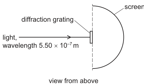
A total of bright dots are formed on the screen.
The grating is at the centre of the semicircle. The lines of the grating are vertical. The separation between adjacent lines in the grating is .
What is a possible value of ?
Options
A
B
C
D
Working
Total bright dots .
For a grating,
Highest order exists when :
Only option in this range is .
Answer
A
A
Background Concept
A diffraction grating produces principal maxima (bright spots) at angles given by
where:
- is the grating spacing (distance between adjacent lines),
- is the wavelength,
- is the order number (an integer ).
A particular order can only exist if a real angle is possible, i.e. if
So the maximum possible order is
Understanding the Question
We are told that a grating is at the centre of a semicircular screen, and a total of 9 bright dots appear on the screen. Because the grating is illuminated normally, the pattern is symmetric about the central (straight-ahead) direction.
That means the bright dots correspond to orders:
- (one central dot),
- and pairs up to some maximum order .
So we can convert “9 dots” into the maximum order present, then use the condition for the existence of that order.
Approach
- Use symmetry to relate the number of dots to via .
- Use the grating condition for the highest visible order.
- Use the fact that the next order is not present to form an inequality range for .
- Check which option lies in that range.
Step-by-Step Reasoning
Because orders are symmetric, the total number of bright dots is
Given ,
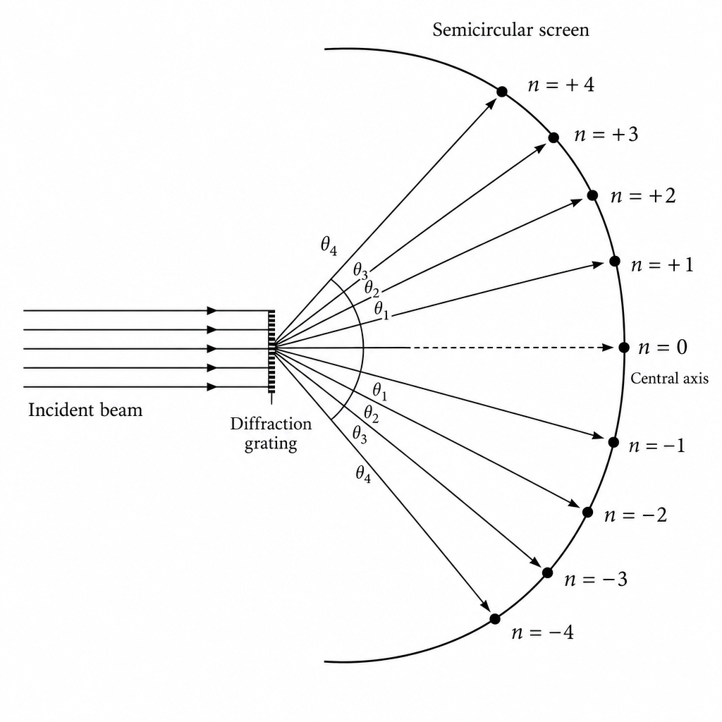
For order to exist, we need a real :
But if order existed, there would be 11 bright dots (orders ). Since there are only 9 dots, order 5 must not exist:
Combine these:
Substitute :
So
Only option A () fits.
Key Takeaways
- Diffraction grating maxima satisfy .
- The highest possible order is limited by , giving .
- Counting bright spots uses symmetry: total spots .
Common Mistakes
- Forgetting the central maximum (), leading to instead of .
- Not using the fact that the next order is absent (you need , not just ).
- Using directly without acknowledging this only corresponds to the limiting case .
Things to Be Careful About
- The screen is semicircular, but the limiting condition is still ; the semicircle just ensures you can “catch” the diffracted beams over a wide angular range.
- Ensure the inequality is the right way round: presence of gives a lower bound; absence of gives an upper bound.
- Keep wavelength in metres to match the answer options.
Which quantity is given by the product of charge and electric potential difference?
Options
A current
B energy transferred
C power dissipated
D resistance
Working
Potential difference is defined by
So
This is the energy transferred.
Answer
B
B
Background Concept
Electric potential difference (p.d.) is defined as the energy transferred (work done) per unit charge moved between two points:
where:
- is potential difference in ,
- is energy transferred in ,
- is charge in .
Rearranging gives , meaning that moving charge through a p.d. transfers energy .
Understanding the Question
You are asked which listed quantity equals “charge potential difference”, i.e. which quantity is given by .
Approach
Start from the definition of potential difference . Rearrange to express in terms of and , then compare with the options.
Step-by-Step Reasoning
- Use the definition:
- Multiply both sides by :
- is energy transferred (work done), so the correct option is energy transferred.
Key Takeaways
- Potential difference is energy per unit charge.
- The product has units , so it corresponds to energy.
Common Mistakes
- Choosing power: power is rate of energy transfer, , not .
- Choosing current: current is rate of flow of charge, .
- Choosing resistance: resistance is .
Things to Be Careful About
- Remember that , so must be in joules.
- Don’t confuse (energy) with (power).
The current in a filament lamp is increased.
Which statement about the lamp is correct?
Options
A The brightness of the lamp decreases.
B The potential difference across the filament decreases.
C The resistance of the filament decreases.
D The temperature of the filament increases.
Working
Increasing current increases power dissipated in the filament:
So the filament heats up and its temperature increases (and its resistance increases, not decreases).
Answer
D
D
Background Concept
A filament lamp has a metal filament whose resistance depends strongly on temperature. When the filament gets hotter, lattice vibrations increase and electrons collide more often, so the resistivity (and hence resistance) increases.
Electrical power converted to thermal energy in the filament is
(and also ). More power means a higher filament temperature, which also generally increases the light output (brightness).
Understanding the Question
We are told the current in the filament lamp is increased and asked which statement must be correct. We need the qualitative effect of increasing current on brightness, potential difference, resistance, and temperature for a filament lamp.
Approach
Use the idea that a larger current causes more power dissipation in the filament, so it heats up. Then use the temperature dependence of a filament’s resistance to judge which options are consistent.
Step-by-Step Reasoning
-
If the current increases, the rate of electrical energy transfer in the filament increases (power increases).
-
Increased power causes the filament to heat up, so the filament temperature rises.
-
For a filament lamp, higher temperature means higher resistance (so any claim that resistance decreases is false).
-
Brightness generally increases with filament temperature (so a claim that brightness decreases is false).
-
The potential difference across the filament does not have to decrease when current increases; typically, to drive more current in a lamp, the applied potential difference is increased. So the only statement that is always correct here is that the temperature increases.
Therefore, the correct option is D.
Key Takeaways
- Filament lamps are non-ohmic because increases as temperature increases.
- Increasing current increases power dissipation, leading to a higher filament temperature.
Common Mistakes
- Thinking resistance decreases when current increases (true for some components like an NTC thermistor, but not for a metal filament).
- Assuming the potential difference must decrease when current increases; in most practical situations it increases to drive more current.
Things to Be Careful About
- A filament lamp’s – curve becomes less steep at higher currents because is increasing.
- Distinguish between components: metal filament (positive temperature coefficient) vs thermistor (usually negative temperature coefficient).
A student builds the circuit shown. All the lamps are identical.
Which lamp dissipates the most power?
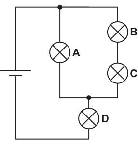
Options
A
B
C
D
Working
Let each lamp have resistance and the cell have p.d. .
Parallel section: is in parallel with which is .
Total resistance:
Circuit current:
Power in lamp :
Voltage across the parallel section:
Power in :
In branch , current so
So is greatest.
Answer
D
D
Background Concept
For identical filament lamps in circuit questions, we treat each lamp as a resistor of the same resistance .
Power dissipated by a component can be found using any of:
In series, the same current flows through each component.
In parallel, the same potential difference (p.d.) is across each branch.
To compare which lamp has the most power, it is usually easiest to:
- reduce the circuit to find the main current and key p.d.s, then
- compute each lamp's power with (if current is known) or (if p.d. is known).
Understanding the Question
The circuit has lamp in series with a parallel combination of:
- one branch containing lamp alone, and
- a second branch containing lamps and in series.
All lamps are identical, so all have the same resistance . We must decide which single lamp dissipates the greatest power.
Approach
- Replace lamps by resistances and combine and (series).
- Combine that series pair in parallel with to get an equivalent resistance for the parallel section.
- Add lamp in series to get total circuit resistance and hence the circuit current .
- Use the current and/or the p.d. across the parallel section to find , , , .
- Compare the expressions.
Step-by-Step Reasoning
-
Treat each lamp as resistance .
-
Series in the right-hand branch:
- Parallel combination of (resistance ) with the branch (resistance ):
- Total resistance is lamp in series with that parallel section:
So the main current from the cell is:
This same current flows through lamp , so its power is
- Find the p.d. across the parallel network:
Lamp is directly across this p.d., so
- For branch , the p.d. across the pair is also , so its branch current is
The same current flows through and through (series), hence
- Compare:
So lamp dissipates the most power.
Key Takeaways
- Identical lamps can be modelled as equal resistances.
- Reduce series-parallel circuits to find main current and key p.d.s.
- Use when the current through a component is known; use when the p.d. across it is known.
- A component in series with a parallel network can have a larger p.d. than the p.d. across each parallel branch.
Common Mistakes
- Assuming the current splits equally between the two parallel branches (it does not, because their resistances are different: and ).
- Forgetting that lamps and share the p.d. across their branch (each gets half of because they are equal resistors in series).
- Comparing brightness using only current or only p.d. without calculating power.
Things to Be Careful About
- Keep track of what is in series and what is in parallel: is in series with the entire parallel section.
- In parallel, p.d. is the same across branches; in series, current is the same through components.
- When using , the must be the p.d. across that specific lamp (not across the whole circuit, and not across the entire branch unless it is a single lamp).
The resistance of a metal cube is measured by placing it between two parallel plates, as shown.
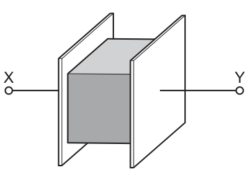
The cube has volume and is made of a material with resistivity . The connections to the cube have negligible resistance.
Which expression gives the electrical resistance of the metal cube between and ?
Options
A
B
C
D
Working
For a conductor,
For a cube of side , volume .
Between opposite faces: and .
Answer
C
C
Background Concept
The resistance of a uniform piece of material depends on:
- its resistivity (a material property),
- the length of the current path,
- the cross-sectional area perpendicular to the current.
They are related by
This formula applies when the current density is roughly uniform and the conductor has constant cross-sectional area along the current direction.
Understanding the Question
A metal cube is clamped tightly between two parallel conducting plates connected to terminals and . The cube fills the space, so current enters one face of the cube from the left plate and leaves from the opposite face into the right plate.
You are given the cube volume (not the side length), and the resistivity . The connections have negligible resistance, so the only significant resistance is through the cube.
We need between and in terms of and .
Approach
- Use .
- Express the cube side length using the volume: .
- Identify (distance between plates through the cube) and (area of the face).
- Substitute and simplify to match one of the options.
Step-by-Step Reasoning
Let the cube side be .
From geometry:
Current flows from one face to the opposite face, so the length of the current path is the cube thickness:
The cross-sectional area perpendicular to current is the area of the face:
Substitute into the resistivity formula:
Now replace by :
This matches option C.
Key Takeaways
- Use for a uniform conductor.
- For a cube, side length is related to volume by .
- Between opposite faces of a cube, and , giving .
Common Mistakes
- Using or (mixing up length and area).
- Forgetting that volume corresponds to , so not .
- Choosing an expression proportional to or , which would imply resistance increases with larger cross-sectional area (opposite of ).
Things to Be Careful About
- Identify the direction of current correctly: it goes through the cube thickness between the plates (one face to the opposite face).
- Keep the distinction clear: is along the current direction; is perpendicular to it.
- Check plausibility: increasing cube size increases faster than , so resistance should decrease with increasing , consistent with .
A circuit needs to be completed by connecting two resistors between points and , as shown.
The resistors can be connected in series or in parallel with each other.
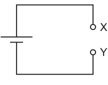
Which combination of resistors produces the least resistance between and ?
Options
| resistances of resistors / | type of combination | |
|---|---|---|
| A | and | parallel |
| B | and | parallel |
| C | and | series |
| D | and | series |
Working
For parallel resistors,
Option A:
Option B:
Series options: so and .
Least resistance is option A.
Answer
A
A
Background Concept
The equivalent resistance between two points is the single resistance that would draw the same current for the same potential difference.
- Series: the same current flows through each resistor, so potential differences add:
- Parallel: the same potential difference is across each branch, and currents add:
A key consequence is that parallel combinations always give an equivalent resistance smaller than the smallest individual resistor.
Understanding the Question
Two resistors are to be connected between the same two points and . The options give two resistor values and whether they are in series or parallel. The task is to find which option gives the smallest equivalent resistance between and .
So we compute the equivalent resistance for each option (A–D) and select the minimum.
Approach
- Use the series formula for options C and D.
- Use the parallel reciprocal formula for options A and B.
- Compare the four equivalent resistances and pick the smallest.
Step-by-Step Reasoning
Option A (20 \Omega and 40 \Omega in parallel):
Option B (40 \Omega and 100 \Omega in parallel):
Option C (20 \Omega and 40 \Omega in series):
Option D (40 \Omega and 100 \Omega in series):
Comparing: , , , .
The smallest is from option A.
Key Takeaways
- In series: resistances add directly.
- In parallel: add reciprocals; the equivalent resistance is less than the smallest resistor.
- For “least resistance” questions, parallel combinations are often (but not always) the smallest; you still need to calculate and compare.
Common Mistakes
- Adding resistors in parallel as (that is only for series).
- Forgetting to invert after adding reciprocals in the parallel calculation.
- Assuming “parallel is always least” without comparing the given values (you must check both parallel options).
Things to Be Careful About
- Use the correct formula for the stated connection (series vs parallel).
- In parallel questions, a quick sense-check is: the answer must be less than the smaller resistor (e.g. for option A it must be less than , and is reasonable).
The diagram shows a circuit that includes a cell with internal resistance.
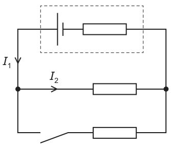
The switch is initially open.
Which row describes the effects on currents and of closing the switch?
Options
| A | decreases | decreases |
| B | decreases | stays the same |
| C | increases | decreases |
| D | increases | stays the same |
Working
Closing the switch adds a resistor branch in parallel with the middle resistor, so the external equivalent resistance decreases.
Total current from the cell () therefore increases.
With internal resistance , the terminal p.d. is
Since increases, decreases, so the current in the middle resistor
decreases.
Answer
C
C
Background Concept
A cell with internal resistance behaves like an ideal emf source in series with a resistor .
If the total current supplied by the cell is , then the voltage available to the external circuit (the terminal p.d.) is reduced by the “lost volts” across :
For resistors in parallel, adding an extra parallel branch decreases the equivalent resistance of the external load.
Understanding the Question
Initially the switch is open, so only the middle resistor is connected as the external load. When the switch is closed, the bottom resistor branch is added in parallel with the middle resistor.
is the current in the main supply line (the total current from the cell into the junction). is the current through the middle resistor.
We must decide how and change when the switch is closed.
Approach
- Decide how the external equivalent resistance changes when the switch closes (parallel effect).
- Use that to infer how the total current from the cell changes.
- Use internal resistance to relate the increased total current to the terminal p.d. across the parallel network.
- Use for the middle resistor to infer the direction of change in .
Step-by-Step Reasoning
When the switch is open, the external circuit is just the middle resistor .
When the switch is closed, the bottom branch (a resistor in series with a closed switch) is connected between the same two rails as the middle resistor, so the middle and bottom resistors are in parallel.
- External equivalent resistance decreases:
Adding a parallel path means
- Total current increases:
The total current from the cell is
Since decreases, the denominator decreases, so increases.
- Terminal p.d. decreases due to internal resistance:
Because increased, the lost volts increase, so across the external parallel network decreases.
- Middle-branch current decreases:
The middle resistor’s resistance is unchanged, so
and since decreases, decreases.
Therefore the correct row is: increases, decreases (option C).
Key Takeaways
- Closing a switch that adds a parallel branch reduces external equivalent resistance.
- With internal resistance present, increasing total current reduces terminal p.d.
- A branch current can decrease even though the total current increases, because the supply voltage across the branches can drop.
Common Mistakes
- Assuming that because “more paths” are available, every branch current must increase.
- Forgetting internal resistance and assuming terminal p.d. stays constant at .
- Treating as the same as even after the second branch is connected.
Things to Be Careful About
- The key subtlety is the change in terminal p.d.: without internal resistance (), the terminal p.d. would remain and would stay the same. Here, , so drops when total current rises.
- Ensure you identify which current is total supply current () and which is a branch current ().
The diagram shows a circuit consisting of a cell and three resistors , and .
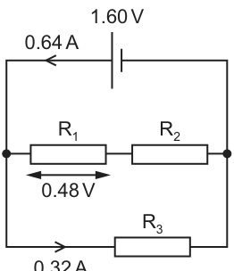
The cell has electromotive force (e.m.f.) and negligible internal resistance. The current in the cell is .
The potential difference across is .
The current in is .
What is the resistance of ?
Options
A
B
C
D
Working
The p.d. across each branch is .
Current in middle branch (through and in series):
p.d. across :
So
Answer
C
C
Background Concept
In a parallel circuit, each branch is connected across the same two nodes, so the potential difference (p.d.) across each branch is the same.
Kirchhoff's first law (junction rule) states that the total current into a junction equals the total current out. So the cell current splits between the parallel branches.
For any resistor (or series combination treated as one component), Ohm's law applies:
For resistors in series, the same current flows through each resistor and the total p.d. across the series combination is the sum of the p.d.s across each resistor.
Understanding the Question
The cell (e.m.f. , negligible internal resistance) is connected across two rails, and there are two parallel branches between the same rails:
- one branch contains and in series,
- the other branch contains .
Given:
- current in the cell is ,
- p.d. across is ,
- current through is .
We need the resistance of .
Approach
- Use Kirchhoff's first law: cell current = current in series branch + current in .
- Use the fact that the p.d. across the series branch equals the cell voltage ().
- Subtract the p.d. across from to get the p.d. across .
- Apply for using the series-branch current.
Step-by-Step Reasoning
1) Find the current in the – branch
The cell supplies total. This splits into the bottom branch () and the middle branch ( and in series).
Given ,
This is the current through both and (because they are in series).
2) Find the p.d. across
Because the internal resistance is negligible, the full e.m.f. appears across the rails, so the p.d. across the series branch is .
In that branch, the p.d.s add:
So
3) Use Ohm's law to find
So the correct option is C.
Key Takeaways
- In parallel, each branch has the same p.d. across it.
- Use Kirchhoff's first law to split the total current into branch currents.
- In series, the same current flows and the p.d.s add.
- Once you have across a resistor and the current through it, use .
Common Mistakes
- Using as the current through (it is the total cell current, not the branch current).
- Forgetting that the series branch has the full across it (since it is in parallel with ).
- Adding to instead of subtracting to find .
Things to Be Careful About
- “Negligible internal resistance” means terminal p.d. equals the e.m.f.; if internal resistance were not negligible, the rail voltage would be less than .
- Keep clear which quantities belong to the whole circuit (cell current) and which belong to one branch (current through , current through the series branch).
- Ensure units: volts for p.d., amperes for current, ohms for resistance.
The diagram shows a potentiometer circuit used to compare the electromotive forces (e.m.f.), and , of two cells.
is a uniform resistance wire. The fixed resistor has resistance .
A sliding contact is moved along the wire . When the sliding contact is at position , the galvanometer reads zero.
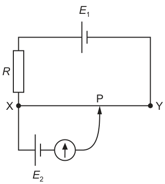
The circuit is changed so that the galvanometer reads zero when the sliding contact is at a new position to the left of .
Which change could have been made to the circuit?
Options
A The wire was replaced with one of lower resistance.
B was increased.
C was decreased.
D was decreased.
Working
At balance (galvanometer reads zero), the p.d. along equals the e.m.f. :
where is the potential gradient along and .
New balance is to the left of so decreases, hence must increase (since is unchanged).
In the driving circuit, decreasing increases the current in , so the p.d. per unit length (potential gradient) increases.
Answer
D
D
Background Concept
A potentiometer uses a steady current through a uniform resistance wire to create a uniform potential gradient (potential drop per unit length).
If the wire has resistance per unit length and the current in the wire is , then the potential gradient is
In a null method, a cell of e.m.f. is connected in opposition to the p.d. across a length of the wire. When the galvanometer reads zero, no current flows through that cell branch, so the p.d. across that length equals the e.m.f.:
Understanding the Question
At position , the galvanometer reads zero, so the p.d. between and equals .
Then the circuit is altered and the new balance point is to the left of , meaning the required balance length has become smaller.
We must choose which change to the circuit could cause a smaller balance length.
Approach
Use the balance condition
and interpret “balance point moves left” as “ decreases”. With not stated to change, a decrease in implies an increase in .
Then decide which option increases the potential gradient along the wire. Since , for the same wire is fixed, so we need an increase in current in the primary circuit (the one containing , , and wire ).
Step-by-Step Reasoning
-
Null condition at
For a uniform wire, is proportional to length :
So initially,
-
New balance point is to the left
Left of means a shorter balance length: decreases.
From
for to decrease (with unchanged), must increase.
-
Which change increases ?
Since the wire is uniform and (in option D) unchanged, is constant, so
The current in the potentiometer wire is set by the supply cell and the total series resistance in the primary circuit. Decreasing reduces total resistance, so increases, hence increases.
-
Check the other options quickly
- Increasing would require a larger balancing p.d., so would increase (move right), not left.
- Decreasing reduces current , hence reduces , so increases (move right).
- Replacing with lower resistance changes both and the circuit current; the effect on is not a definite increase, so it cannot be confidently linked to a left shift.
Therefore the definite change producing a left shift is decreasing .
Key Takeaways
- At null deflection in a potentiometer, the unknown e.m.f. equals the p.d. along the balancing length: .
- Moving the balance point left means a smaller , which corresponds to a larger potential gradient (if is unchanged).
- In a series circuit, reducing resistance increases current, increasing the potential gradient along the potentiometer wire.
Common Mistakes
- Thinking “left” means larger potential difference; along a uniform wire, shorter length means smaller p.d.
- Assuming changing changes the balance length in the same direction as (they act differently: sets , sets the required p.d.).
- Forgetting that the potentiometer works as a null method: at balance, no current flows in the branch.
Things to Be Careful About
- Use the correct proportionality: only if is constant; after a circuit change, may change.
- Distinguish between changing the test e.m.f. () and changing the potential gradient (set by the primary circuit containing , , and the wire).
- When assessing wire changes (option A), note that both current and resistance-per-length can change, so the direction of change in may not be definite without extra information.
Nucleus has neutrons and protons. Nucleus is unstable and undergoes -decay to form nucleus . Nucleus then undergoes decay to form nucleus .
Nucleus is represented by point on the graph.
Which point on the graph represents nucleus ?
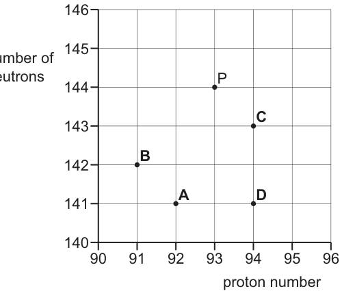
Options
A
B
C
D
Working
Start: , .
-decay: , so : , .
-decay: , so : , .
Point with is .
Answer
A
A
Background Concept
Nuclei are characterised by proton number and neutron number (with nucleon number ).
Key decay changes:
- -decay emits a helium nucleus . So the parent nucleus loses 2 protons and 2 neutrons:
- decay is when a neutron changes into a proton (plus an electron and an antineutrino). So:
- stays the same.
Understanding the Question
Point represents nucleus with protons and neutrons (so it sits at on a graph of proton number vs neutron number).
You must follow two decays in order:
- by -decay.
- by decay.
Then identify which labelled point , , , or corresponds to the final of nucleus .
Approach
Update step-by-step:
- Apply -decay rules to move from to .
- Apply decay rules to move from to .
- Find the point on the graph with the final proton number and neutron number.
Step-by-Step Reasoning
For nucleus :
After -decay (, ):
After decay (, ):
So nucleus must be at . On the given graph, the labelled point at proton number and neutron number is point .
Key Takeaways
- -decay moves a nucleus two squares left (lower ) and two squares down (lower ) on a vs graph.
- decay moves a nucleus one square right (higher ) and one square down (lower ), with unchanged.
- Tracking directly is often quickest when a graph is in terms of protons and neutrons.
Common Mistakes
- Swapping the direction for decay (some students incorrectly do ).
- Forgetting that decay changes both and (not just ).
- Applying both decays to the original nucleus without updating after the first decay.
Things to Be Careful About
- Ensure you are using the correct axes: horizontal is proton number and vertical is neutron number .
- Remember: in decay, stays constant but and change.
- When matching to points, check you have the coordinate in the order , not .
The diagrams show the quark composition of four different hadrons. One of the hadrons is a particle. It has a charge of , where is the elementary charge.
Which hadron could be the particle?

Working
Up quark charge , down quark charge , strange quark charge .
For option D ():
Answer
D
D
Background Concept
Hadrons are particles made of quarks.
- Baryons contain three quarks (e.g. , , etc.).
- Each quark has a fixed electric charge:
- up quark :
- down quark :
- strange quark :
The total charge of a hadron is found by adding the charges of its constituent quarks.
Understanding the Question
You are shown four different three-quark (baryon) compositions labelled A–D. One of them is a particle, and the question tells you its charge is .
So you need to check which option has total charge when you add its three quark charges.
Approach
- Write down the charges of , , and .
- For each option, add the three quark charges.
- Pick the option whose total equals .
Step-by-Step Reasoning
Using , , :
- A:
- B:
- C:
- D:
Only option D gives charge , so it could be the particle.
Key Takeaways
- Baryon charge is the sum of its three quark charges.
- Remember: is positive (), while and are negative ().
- A total charge of here requires two quarks and one quark.
Common Mistakes
- Mixing up the strange quark charge (it is not ; it is ).
- Adding fractions incorrectly (e.g. treating ).
- Forgetting that the question asks for (not or ).
Things to Be Careful About
- Always factor out and add the numerical fractions first.
- Check that each option is three quarks (so they are all baryons), so simple charge addition applies directly.
- Ensure the final charge is exactly (not just “positive”).
Which type of particle is comprised of the most quarks?
Options
A antiquark
B baryon
C lepton
D meson
Working
An antiquark is a single quark constituent ().
A meson is made of a quark and an antiquark ().
A baryon is made of three quarks ().
A lepton contains no quarks ().
So the particle type comprised of the most quarks is a baryon.
Answer
B
B
Background Concept
In the quark model, particles are classified by whether they are made from quarks.
- Quarks (and antiquarks) are fundamental constituents in this model.
- Hadrons are particles made of quarks. They come in two common families:
- Baryons: made of three quarks () (or three antiquarks for antibaryons).
- Mesons: made of a quark and an antiquark ().
- Leptons (e.g. electron, muon, neutrino) are not made of quarks.
So, to compare “how many quarks”, you just recall these compositions and count constituents.
Understanding the Question
You are given four particle types and asked which type is comprised of the most quarks. That means the largest number of quark/antiquark constituents in its standard quark-model structure.
Options:
- antiquark
- baryon
- lepton
- meson
Approach
- Recall the constituent structure for each type.
- Count the number of quark/antiquark constituents.
- Choose the option with the greatest count.
Step-by-Step Reasoning
- Antiquark: this is one constituent, i.e. , so it contains 1 (anti)quark.
- Meson: structure is , so it contains 2 constituents.
- Baryon: structure is , so it contains 3 quarks (antibaryons have , still 3 constituents).
- Lepton: leptons are fundamental in the Standard Model but are not made of quarks, so contain 0 quarks.
The largest number is 3, so the correct option is baryon.
Key Takeaways
- Baryons are (3 quarks).
- Mesons are (2 constituents).
- Leptons contain no quarks.
- An antiquark is just one constituent.
Common Mistakes
- Confusing baryons with mesons and swapping their quark counts.
- Thinking leptons are made of quarks because they are “particles” in general.
- Forgetting that an antiquark is a single constituent, not a composite particle type.
Things to Be Careful About
- The question asks “type of particle” (baryon/meson/lepton) versus a single constituent (antiquark). Still, you answer by counting constituents.
- “Most quarks” here means the most quark/antiquark constituents in the quark model (so baryons/antibaryons both correspond to 3 constituents).
Your score so far
Answer a question to start scoring
Your marks add up here as you work through the paper.