Physics 9702/44 — May/June 2025
Cambridge A-Level · A Level Structured Questions · worked solutions for every part, with the mark scheme
Topics Oscillations · Capacitance · Magnetic Fields · Gravitational Fields · Temperature · Ideal Gases · +7 more
Answer
A gravitational field is a region of space in which a mass experiences a gravitational force.
A gravitational field is a region of space in which a mass experiences a gravitational force.
Background Concept
A field describes how an object placed in a region would experience a force. For gravity, masses interact at a distance: a mass produces a gravitational influence around it.
It is also common to quantify the field using the gravitational field strength , defined as force per unit mass:
Understanding the Question
You are asked to define gravitational field (not ). So you should give a statement describing what exists in space around masses.
Approach
Write a one-sentence definition: “region where a mass experiences gravitational force”. Avoid writing an equation unless asked.
Step-by-Step Reasoning
- The key idea is: if you place a small test mass in that region, it feels a force due to gravity.
- Therefore the region is described as a gravitational field.
Key Takeaways
- A gravitational field is defined by its effect: it exerts a gravitational force on a mass placed in it.
Common Mistakes
- Defining gravitational field strength () when the question asks for gravitational field.
- Missing the idea of “force on a mass placed in the region”.
Things to Be Careful About
- Keep it concise and in words; one clear statement is enough for 1 mark.
The gravitational field strength at a distance from the centre of a uniform spherical planet of mass is given by the expression
where is the gravitational constant and distance is greater than the radius of the planet.
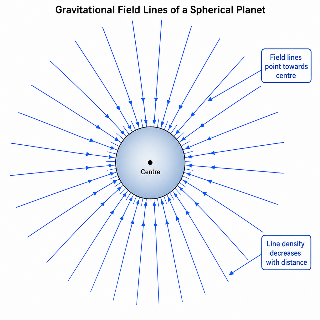
Describe the pattern of the field lines outside the planet that represent the gravitational field due to the planet.
Answer
Field lines are radial and directed towards the centre of the planet. They are closer together near the planet and become more widely spaced with increasing distance.
Field lines are radial and directed towards the centre of the planet, with line density decreasing with distance.
Background Concept
Field lines are a representation of a field. The rules are:
- The arrow on a field line shows the direction of the force on a small test mass.
- The spacing (density) of field lines indicates the magnitude of the field (closer lines = stronger field).
For a spherically symmetric mass, the gravitational field is the same in all directions at a given radius, so the field must be radial.
Understanding the Question
You are told the planet is a uniform sphere and you are considering points outside it ( greater than the radius). You must describe what the gravitational field lines look like in space around the planet.
Approach
Use symmetry + the “field line rules”:
- direction: gravity is attractive, so lines point towards the mass.
- pattern: spherical symmetry means radial lines.
- spacing: because , the field weakens with distance, so lines spread out.
Step-by-Step Reasoning
- Since the field only depends on distance from the centre (), the pattern must be the same at every angle: radial lines.
- A test mass is pulled towards the planet, so arrows point inward.
- As increases, decreases (inverse-square), so the number of lines crossing a given area effectively decreases: the lines are more widely spaced further from the planet.
Key Takeaways
- Outside a spherical mass: field lines are radial and point towards the centre.
- Field strength decreases with distance, shown by decreasing line density.
Common Mistakes
- Drawing circular (tangential) lines instead of radial lines.
- Having arrows pointing away from the planet (would represent repulsion).
- Keeping the spacing constant even though changes with .
Things to Be Careful About
- This question is specifically for outside the planet, so you should not discuss the inside-field variation.
- Include both: (i) direction and (ii) change of spacing, to access full marks.
Explain why, for small changes in vertical height near the surface of the planet, may be assumed to be constant.
Answer
Near the surface, and a small change in height gives only a very small fractional change in .
Since
a small fractional change in produces an even smaller change in , so may be taken as constant for small height changes.
Because near the surface a small height change makes a negligible fractional change in distance from the centre, and since , the change in is negligible.
Background Concept
Outside a spherical planet,
So depends on the distance from the centre, not on height above ground directly. The inverse-square form means decreases as you move away.
For small changes, it is useful to think in terms of fractional (percentage) change:
- If changes by a tiny fraction, changes by about twice that fraction (because of the power 2).
Understanding the Question
“Near the surface” means is about the planet radius (which is very large). “Small changes in vertical height” means is tiny compared with .
You must explain why, in that situation, treating as constant is a good approximation.
Approach
Compare and :
- when , the ratio is almost 1.
- since , the corresponding change in is negligible.
Step-by-Step Reasoning
Let at the surface. A small height change gives where .
Because
we can compare:
If is very small compared with , then is only very slightly bigger than , so the ratio is very close to 1, meaning .
So for everyday heights compared with the Earth’s radius, the change in is too small to matter, and we can treat as constant.
Key Takeaways
- The reason is geometric: the Earth’s radius is huge, so small heights barely change distance to the centre.
- Inverse-square dependence makes the change in small for small fractional changes in .
Common Mistakes
- Saying “ is constant because gravity is constant” without referencing .
- Confusing height above ground with distance from the centre (the formula uses ).
Things to Be Careful About
- Always relate “small height” to “”. That comparison is the heart of the argument.
- Do not claim is exactly constant; it is approximately constant over small height ranges.
Assume that the Earth is a uniform sphere. For the Earth, the product is equal to .
Determine a value, to three significant figures, for the radius of the Earth.
= ______
Working
At the surface,
so
Answer
6.38 × 10^6 m
Background Concept
For a spherically symmetric mass, the gravitational field strength at distance from the centre is
At the planet’s surface, (the radius), so
Understanding the Question
You are given . To find the Earth’s radius , you must use the surface value of (commonly taken as ).
Unknown: .
Approach
Use
and rearrange to make the subject, then substitute the values and quote the result to 3 s.f.
Step-by-Step Reasoning
Starting point:
Rearrange:
so
Substitute:
Compute inside the root:
Then
The unit is metres because the expression inside the square root has units:
and the square root gives .
Key Takeaways
- At the surface of a spherical planet, and are related by .
- Rearranging an inverse-square law often introduces a square root.
Common Mistakes
- Forgetting the square root and using .
- Using without matching the required significant figures (usually fine, but check expectations).
- Giving the answer in km without converting or without stating the unit.
Things to Be Careful About
- Use consistent SI units throughout.
- Quote to three significant figures as asked.
- Make sure the final unit is , not .
Calculate the gravitational potential at the Earth’s surface. Give a unit with your answer.
gravitational potential = ______ unit ______
Working
Gravitational potential at distance from the centre:
At the Earth’s surface :
Answer
−6.25 × 10^7 J kg−1
Background Concept
Gravitational potential at a point is the work done per unit mass in bringing a small test mass from infinity to that point (with no change in kinetic energy). For a spherical mass (or point mass) of mass , outside the sphere:
The negative sign appears because gravity is attractive and we take at infinity.
Unit: since it is energy per unit mass, has units .
Understanding the Question
You have already found the Earth’s radius in part (i). You are asked for the gravitational potential at the Earth’s surface, so use in , with given.
Approach
- Write .
- Substitute and .
- Keep the negative sign and quote the correct unit.
Step-by-Step Reasoning
Use the formula:
At the surface, and :
Calculate:
So
Check units:
Key Takeaways
- Outside a spherical body, gravitational potential is .
- Gravitational potential is negative if zero is chosen at infinity.
Common Mistakes
- Missing the negative sign.
- Giving units as instead of .
- Using (confusing potential with field strength).
Things to Be Careful About
- Use the radius from part (i) consistently.
- Do not round too early; keep enough significant figures to give a 3 s.f. final value if appropriate.
- Ensure your final power of ten is correct when dividing standard form numbers.
Answer
Gravitational potential energy is defined to be zero when the masses are infinitely far apart. Since gravity is attractive, energy must be supplied (work done against the force) to separate them to infinity, so at any finite separation the potential energy is less than zero:
so is always negative.
Because zero is taken at infinity and the gravitational force is attractive, the potential energy at any finite separation is below zero (e.g. ).
Background Concept
Gravitational potential energy of a pair of masses is defined via the work done to move them. A standard convention is:
- Take when the two masses are infinitely separated.
For two point masses and separated by distance :
The sign comes from the fact that gravity is an attractive force.
Understanding the Question
You must explain why gravitational potential energy is always negative for two point masses (with the usual convention at infinity). This is a conceptual sign question.
Approach
Use one (or both) of these arguments:
- The formula directly shows it is negative.
- Work/energy argument: to separate the masses to infinity you must do positive work against attraction, so the initial energy at finite separation must be lower than the zero level at infinity.
Step-by-Step Reasoning
- If the masses are at separation , they attract each other.
- If you slowly pull them apart to infinity (so kinetic energy doesn’t change), you must supply energy because you are doing work against the attractive gravitational force.
- That means the potential energy increases from its value at up to the value at infinity.
- Since we define the value at infinity as , the value at finite must be below this:
This matches the mathematical expression:
where , , , and are all positive, so the result is always negative.
Key Takeaways
- The negativity comes from (i) the choice of zero at infinity and (ii) the attractive nature of gravity.
- At finite separation, the system is “bound”; you must add energy to separate it completely.
Common Mistakes
- Saying “it’s negative because of the minus sign” without connecting to the physical meaning (zero at infinity and attraction).
- Choosing the zero level at the Earth’s surface (a different convention) and then getting confused about signs.
Things to Be Careful About
- The statement “always negative” assumes the standard convention at infinite separation, which is what A-Level uses.
- Distinguish gravitational potential (per unit mass) from gravitational potential energy (energy for a particular pair of masses).
Answer
Two objects are in thermal equilibrium when they are at the same temperature and there is no net transfer of thermal energy between them.
Same temperature and no net heat transfer between them.
Background Concept
Thermal equilibrium is a state related to temperature and heat transfer. Temperature indicates the direction of net thermal energy transfer: if two bodies at different temperatures are placed in thermal contact, thermal energy flows from the higher temperature body to the lower temperature body.
When no net thermal energy transfer occurs between two bodies in contact, their temperatures are equal and they are said to be in thermal equilibrium.
Understanding the Question
You are asked to state what it means for two objects to be in thermal equilibrium. This is a definition-type question worth 2 marks, so two distinct points are expected.
Approach
Give the two standard marking points:
- same temperature, and
- no net heat flow (no net transfer of thermal energy) between them.
Step-by-Step Reasoning
- If object A is hotter than object B, there will be a net transfer of thermal energy from A to B.
- This transfer continues until both objects reach the same temperature.
- At that point, energy transfers may still occur microscopically in both directions, but they balance, so the net transfer is zero.
- Therefore, the definition requires both equal temperature and zero net heat transfer.
Key Takeaways
- Thermal equilibrium implies equal temperature.
- Equal temperature implies no net heat transfer between objects in contact.
Common Mistakes
- Saying only "same temperature" and not mentioning "no net heat transfer" (often loses 1 mark).
- Saying "no heat transfer" without "net" (some transfer occurs both ways microscopically; examiners usually want the phrase "no net transfer").
Things to Be Careful About
- Use the wording "no net transfer of thermal energy" (or "no net heat flow").
- Make it clear the statement refers to the situation when the objects are in thermal contact (or able to exchange thermal energy).
A mass of ice at is placed in a beaker containing a mass of water at Celsius temperature . The beaker is perfectly insulated and has negligible heat capacity. After some time, the ice that was added reaches thermal equilibrium with the original water in the beaker.
The specific latent heat of fusion of water is . The specific heat capacity of water is . The final Celsius temperature of the system is .
Give expressions, in terms of some or all of , , , , and , for the thermal energy:
Answer
E1 = XL
Background Concept
When a substance changes phase at constant temperature, thermal energy is transferred without a temperature change. For melting (fusion), the thermal energy required is
where is the mass that melts and is the specific latent heat of fusion.
Understanding the Question
Ice of mass at melts to become water at . You are asked for the thermal energy gained by the ice during this melting process.
Approach
Use with and given as the specific latent heat of fusion of water.
Step-by-Step Reasoning
- The ice is at the melting point, so the temperature stays at while it melts.
- The energy needed to melt mass is
Key Takeaways
- Melting at the melting point uses latent heat: .
- No temperature change occurs during the phase change.
Common Mistakes
- Using instead of for melting.
- Using the wrong mass (e.g. using instead of ).
Things to Be Careful About
- The temperature remains during melting; only after melting can the water warm up.
Answer
E2 = Mc(t − θ)
Background Concept
For a temperature change with no phase change, the thermal energy transferred is
where is mass, is specific heat capacity, and is the temperature change (final minus initial if you are keeping a sign, or a magnitude if you are calculating “energy lost”).
Understanding the Question
The original water has mass and cools from Celsius temperature down to the final equilibrium temperature . You are asked for the thermal energy lost by this water.
Approach
Compute the magnitude of the temperature decrease: . Then apply with .
Step-by-Step Reasoning
- The water cools, so its temperature decreases from to .
- Magnitude of temperature drop is .
- Hence energy lost is
Key Takeaways
- For cooling/heating without phase change, use .
- For “energy lost”, use a positive magnitude for the temperature drop.
Common Mistakes
- Writing , which is negative if interpreted as energy lost.
- Using instead of for the mass of the water that cools.
Things to Be Careful About
- The question asks for energy lost (a positive quantity), so use as the temperature change magnitude.
- is the specific heat capacity of water, so it applies to both the original water and the melted ice once it is liquid water.
Answer
E3 = Xcθ
Background Concept
Once the ice has melted, it becomes liquid water at . If its temperature then rises to , the energy gained is calculated using
Understanding the Question
You are asked for the thermal energy gained by the melted ice (now water) as it warms from to .
Approach
Use with mass and .
Step-by-Step Reasoning
- After melting, the mass of water formed from the ice is still .
- The temperature rise is from to , so .
- Therefore,
Key Takeaways
- After melting, treat the melted ice as water with the same .
- A rise from to gives .
Common Mistakes
- Using instead of .
- Forgetting that the melted ice starts at , so is , not .
Things to Be Careful About
- This part is only the warming of the melted ice; the melting energy is accounted for separately in .
Use your answers in (b) to show that the final Celsius temperature of the system is given by
Working
Perfect insulation and negligible beaker heat capacity give
So
Expand and collect terms:
Hence
Answer
θ = (Mct − XL) / (c(M + X))
Background Concept
For calorimetry problems (mixing, melting, heating), the key idea is conservation of energy.
- In an insulated system, there is no thermal energy transfer to the surroundings.
- If the container’s heat capacity is negligible, it does not absorb a significant amount of energy.
Therefore, thermal energy lost by the hotter part equals thermal energy gained by the colder part(s).
The relevant equations are:
and
Understanding the Question
Ice of mass at is added to water of mass at temperature . Eventually, everything reaches a common final temperature .
During the process:
- the ice melts at (energy gained),
- the original water cools from to (energy lost),
- the melted ice (now water) warms from to (energy gained).
You must use these to show the provided formula for .
Approach
- Write an energy balance using insulation:
heat lost by original water = heat gained in melting + heat gained in warming melted water. - Substitute the expressions from (b):
, , . - Rearrange to make the subject and match the required expression.
Step-by-Step Reasoning
Because the beaker is perfectly insulated and has negligible heat capacity:
Substitute each expression:
Now expand the left side:
Gather the terms without on one side and the terms on the other. Add to both sides:
Factor out on the right (since ):
Subtract from both sides:
Finally divide by :
This is exactly the expression required.
Key Takeaways
- In an insulated mixing problem: heat lost = heat gained.
- Separate phase change energy () from temperature change energy ().
- When multiple bodies gain energy, add their gains and equate to the loss.
Common Mistakes
- Forgetting one of the gain terms (often missing the warming of the melted ice, ).
- Using instead of when treating energy lost as a positive quantity.
- Including the beaker’s heat capacity even though it is stated negligible.
- Algebra slip when collecting terms (e.g. writing instead of ).
Things to Be Careful About
- The final temperature is for both portions of water (original and melted ice).
- The melted ice starts warming only after it has melted, so the heating term uses mass and temperature rise .
- Keep signs consistent: treat , , as positive magnitudes and use the balance .
Answer
An ideal gas is a gas in which:
- molecules have negligible volume and exert no intermolecular forces (except during collisions), and
- collisions are perfectly elastic (so it obeys ).
An ideal gas has molecules of negligible volume with no intermolecular forces (except during collisions), undergoing perfectly elastic collisions so that it obeys pV = nRT.
Background Concept
An ideal gas is a model used to simplify real gas behaviour. In the kinetic theory model, gas molecules are treated as point particles moving randomly.
The key assumptions are:
- the molecules occupy negligible volume compared with the container volume,
- there are no intermolecular forces except during collisions,
- collisions between molecules and with the container walls are perfectly elastic (kinetic energy is conserved in each collision),
- molecules move in random directions with a wide range of speeds.
Under these assumptions, the gas obeys the equation of state
(or equivalently ).
Understanding the Question
The question asks you to state what is meant by an ideal gas (2 marks). That means giving a concise definition with the essential assumptions (typically any two correct points are enough).
Approach
Provide two clear, standard points from the ideal-gas assumptions, and (optionally) link them to the fact that an ideal gas obeys .
Step-by-Step Reasoning
- State a microscopic assumption: e.g. negligible molecular volume and/or no intermolecular forces.
- State another: e.g. collisions are perfectly elastic.
- Optionally mention the macroscopic consequence: the gas obeys .
Any two of these core points usually secure full credit.
Key Takeaways
- “Ideal gas” is defined by assumptions about molecules and collisions, not by a particular substance.
- Ideal gases obey because of those assumptions.
Common Mistakes
- Saying only “it obeys ” with no assumptions (often not enough on its own).
- Confusing with “incompressible” (gases are compressible).
- Mentioning temperature/pressure conditions without stating the model assumptions.
Things to Be Careful About
- Use the phrasing “no intermolecular forces except during collisions” (forces act during collisions to change momentum).
- If you mention , make sure it’s in addition to at least one microscopic assumption to secure the definition marks.
An ideal gas at a pressure of has a density of .
Show that the root-mean-square (r.m.s.) speed of molecules of this gas is approximately .
Working
For an ideal gas,
Answer
(about ).
5.0 × 10^2 m s^-1
Background Concept
Kinetic theory links macroscopic pressure to microscopic molecular motion. For a gas of density in which molecules have a range of speeds, the pressure is related to the root-mean-square speed by
where:
- is the gas pressure,
- is the mass density of the gas,
- is the square root of the mean of the squared speeds.
This formula comes from molecules repeatedly colliding elastically with the container walls; the factor arises because only one-third of the random motion contributes, on average, to any given direction.
Understanding the Question
You are given:
and asked to show that is approximately . So the method is implied: use the kinetic theory relation between , and .
Approach
- Start from
- Rearrange for .
- Substitute the given values.
- Evaluate and round to an appropriate significant figure to demonstrate “approximately ”.
Step-by-Step Reasoning
Start with the kinetic theory equation:
Rearrange:
Now substitute:
Take the square root:
So is indeed about .
Key Takeaways
- Use the kinetic theory link: .
- Rearranging gives .
- Always keep track of units: works consistently with in to give speed in .
Common Mistakes
- Forgetting the factor of (giving a speed too small by a factor of ).
- Using instead of .
- Rounding too early (though here “approximately 500” allows some rounding).
Things to Be Careful About
- is a speed (scalar), so no direction is needed.
- Don’t confuse with mean speed; the kinetic theory relation specifically uses mean square speed.
One molecule of the gas has a mass of .
Determine the thermodynamic temperature of the gas.
temperature = ______
Working
Average translational kinetic energy:
Using , and :
Answer
temperature
2.8 × 10^2 K
Background Concept
For an ideal gas, temperature is linked to the average translational kinetic energy of molecules:
Also,
Combining these gives
where:
- is the mass of one molecule,
- is the Boltzmann constant (),
- is thermodynamic temperature in kelvin.
Understanding the Question
You are told one molecule has mass and, from part (i), the gas has . You must find .
Approach
- Use
- Rearrange for .
- Substitute values and evaluate.
Step-by-Step Reasoning
Start from the energy–temperature relation:
Cancel the factor of :
So
Substitute the given values:
Therefore:
So the temperature is about .
Key Takeaways
- Temperature measures average translational kinetic energy: .
- Using is natural because .
Common Mistakes
- Using instead of .
- Forgetting the factor of 3 (using ).
- Mixing up and (here you are working per molecule, so use ).
Things to Be Careful About
- Use kelvin for thermodynamic temperature (not degrees Celsius).
- The final value should be sensible: corresponds to “room temperature”, consistent with molecular speeds of a few hundred .
Working
For an ideal gas, intermolecular potential energy is negligible, so internal energy is the total random kinetic energy.
Average translational kinetic energy per molecule is , hence for moles:
With , and :
Answer
2.1 × 10^4 J
Background Concept
The internal energy of a substance is the sum of the random microscopic energies of its particles:
- random kinetic energy (translational, rotational, vibrational),
- plus any microscopic potential energy due to intermolecular forces.
For an ideal gas, one key assumption is that there are no intermolecular forces (except during collisions). That means the intermolecular potential energy is negligible, so depends only on the random kinetic energy.
From kinetic theory, the average translational kinetic energy per molecule is
For molecules,
Using and gives the molar form:
(This is the form typically expected at this level when modelling the gas as having only translational degrees of freedom.)
Understanding the Question
You must calculate the internal energy of of the same gas as in part (b), so you use the temperature found in (b)(ii), about . The question also asks you to explain your reasoning, i.e. why can be written in terms of .
Approach
- State the ideal-gas reasoning: negligible intermolecular potential energy, so is kinetic energy only.
- Use the kinetic theory result for average kinetic energy, leading to
- Substitute and your value of .
Step-by-Step Reasoning
Because the gas is ideal, intermolecular potential energy is negligible. Internal energy is therefore just the total random kinetic energy.
Average translational kinetic energy per molecule:
Total for molecules:
Convert to moles using :
Now substitute , , and :
Compute stepwise:
So
Key Takeaways
- For an ideal gas, internal energy depends only on temperature because potential energy is negligible.
- The standard model used here gives .
Common Mistakes
- Using (missing the factor ).
- Forgetting to use kelvin.
- Using with moles (if you use , you must use number of molecules , not moles).
Things to Be Careful About
- Quote in joules and to sensible significant figures (typically 2 or 3).
- Ensure consistency: the temperature used should be the same as in part (b)(ii), or error-carried-forward should be clear.
- The justification must explicitly link “ideal gas” to “negligible potential energy”, which is why depends on only.
Answer
Simple harmonic motion is motion in which the acceleration is proportional to the displacement from the equilibrium position and is directed towards the equilibrium position:
Acceleration is proportional to displacement from equilibrium and directed towards equilibrium: a = -ω^2 x.
Background Concept
In oscillatory motion, an object moves back and forth about an equilibrium position. Simple harmonic motion (SHM) is a special type of oscillation where the restoring effect becomes stronger the further you are from equilibrium.
The defining condition for SHM is that the acceleration (and hence resultant force) is:
- directly proportional to the displacement from equilibrium, and
- opposite in direction to the displacement (i.e. always towards equilibrium).
Mathematically this is written as
where:
- is acceleration,
- is displacement from equilibrium,
- is the angular frequency (a constant for the motion).
Understanding the Question
You are not asked to do any calculation: you must state what SHM means. For full marks, you must include both:
- proportionality to displacement, and 2) direction towards equilibrium (negative sign).
Approach
Write the defining equation or its worded equivalent. Make sure the "towards equilibrium" part is clear (this is what the minus sign represents).
Step-by-Step Reasoning
- "Acceleration proportional to displacement" means .
- "Directed towards equilibrium" means if is positive, must be negative, and vice versa, so .
- The constant of proportionality is written as , giving .
Key Takeaways
- SHM is defined by the relationship between and , not by the object being a pendulum or having a sine graph.
- The negative sign (towards equilibrium) is essential.
Common Mistakes
- Saying only "it moves in a sine wave" (not a definition).
- Missing the direction (writing instead of ).
- Stating "velocity proportional to displacement" (wrong: velocity is largest at equilibrium where ).
Things to Be Careful About
- Use the word equilibrium explicitly.
- Make clear it is the acceleration (or restoring force) that is proportional to displacement.
A small sphere is suspended from a fixed point P by a string of negligible mass, as shown in Fig. 4.1.
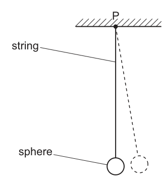
The sphere is given a small horizontal displacement and is then released.
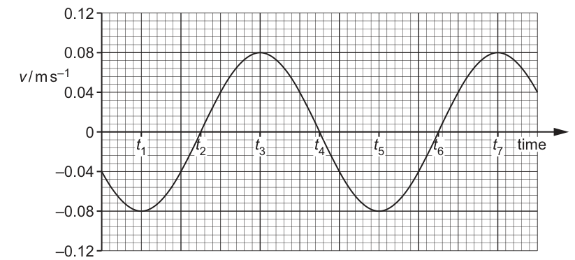
The variation with time of the horizontal velocity of the sphere is shown in Fig. 4.2.
State two times at which the sphere is passing in the same direction through the equilibrium position.
time ______ and time ______
Answer
At the equilibrium position the speed is maximum, so this corresponds to peaks/troughs of the – graph.
Two suitable times are and (both have negative maximum velocity, so the sphere passes equilibrium in the same direction).
t1 and t5
Background Concept
In SHM, the relationship between displacement and velocity is such that:
- At equilibrium (), the acceleration is zero and the speed is maximum.
- At the extremes (), the speed is zero.
So, on a velocity–time graph:
- Crossing indicates turning points (maximum displacement).
- Maximum positive or negative indicates passing through equilibrium.
The direction of motion is given by the sign of (positive or negative).
Understanding the Question
You are given a graph of horizontal velocity against time. The question asks for two times when the sphere is:
- at the equilibrium position (so horizontal displacement is zero), and
- moving through it in the same direction (so velocity must have the same sign at those two times).
Approach
- Find times of maximum magnitude of velocity (peaks/troughs) because those correspond to equilibrium.
- Choose two times where the velocity has the same sign (both positive peaks or both negative troughs).
Step-by-Step Reasoning
- From the sinusoidal – curve, the trough at is the most negative value of , so this is an equilibrium crossing with motion in the negative direction.
- The next trough occurs at , also most negative, so this is again an equilibrium crossing in the same (negative) direction.
- Therefore, and satisfy the requirement.
(Equally acceptable would be and , which are both positive peaks.)
Key Takeaways
- In SHM, equilibrium corresponds to maximum speed, not zero speed.
- The sign of tells you the direction of travel.
Common Mistakes
- Choosing (these are where , i.e. turning points, not equilibrium).
- Choosing one maximum and one minimum (directions opposite).
Things to Be Careful About
- The question says "passing ... through the equilibrium position" which implies it is moving (so ).
- Use the velocity sign to ensure "same direction".
The time interval between and is .
Calculate the frequency of oscillation of the sphere.
frequency = ______
Working
From the – graph: is a minimum and is the next-but-one zero crossing, so
Given ,
Answer
0.57 Hz
Background Concept
Oscillations repeat in time with a period (time for one full cycle). The frequency is
For a sinusoidal velocity–time graph, particular features repeat every fixed fraction of a period:
- Minimum next zero crossing:
- Minimum maximum:
- Minimum next minimum:
Understanding the Question
You are told that the time between and is . From the graph:
- is a minimum of velocity.
- is a zero crossing after the next minimum ().
You must convert this time gap into the period , then find .
Approach
- Decide what fraction of a full cycle corresponds to the interval .
- Use that to calculate .
- Use .
Step-by-Step Reasoning
- From the graph sequence: minimum at , then later another minimum at . So
- From a minimum to the next time the curve crosses zero is a quarter period, so
- Therefore the total from to is
- Substitute the given :
- Then the frequency is
Key Takeaways
- A sinusoidal graph lets you find even if you are not given two identical points directly, by using fractions of the cycle.
- Use .
Common Mistakes
- Assuming is exactly one period.
- Mixing up quarter-period and half-period steps between maxima/minima/zero crossings.
- Writing instead of .
Things to Be Careful About
- Identify the features correctly: is a trough, is a zero crossing.
- Give frequency in and to a sensible number of significant figures (typically 2 s.f. here).
The sphere in (b) is undergoing simple harmonic motion.
Use your answer in (b)(ii) and data from Fig. 4.2 to determine the maximum displacement of the sphere from its equilibrium position.
maximum displacement = ______
Working
From Fig. 4.2, maximum horizontal speed .
Using with ,
For SHM,
Answer
3.4 × 10^-2 m
Background Concept
In SHM, displacement and velocity vary sinusoidally. If we write
then differentiating gives velocity
So the maximum speed is
Also, angular frequency is related to frequency by
Understanding the Question
You have already found the frequency (from part (b)(ii)). You are now told the motion is SHM and must use:
- your value of to find ,
- the velocity–time graph to read ,
- then calculate the maximum displacement (the amplitude) .
Approach
- Read the velocity amplitude from the graph (the peak value).
- Convert into using .
- Rearrange to get .
Step-by-Step Reasoning
- From Fig. 4.2, the peaks of the sinusoidal velocity curve give . Reading from the vertical scale gives approximately .
- With ,
- Use the SHM amplitude relation:
- Rounding appropriately gives .
Key Takeaways
- For SHM, the link between velocity amplitude and displacement amplitude is .
- You often use a graph to obtain an amplitude (here, ).
Common Mistakes
- Using but forgetting the .
- Reading from a zero crossing (wrong: at turning points, not maximum speed).
- Mixing up and (units: in , in ).
Things to Be Careful About
- Ensure you read the peak of the curve, not the axis limit.
- Use consistent units: in gives in .
- Quote the final answer to a sensible number of significant figures based on the graph reading.
Answer
Electric potential at a point is the work done per unit positive charge in bringing a small test charge from infinity to that point (without change in kinetic energy).
Work done per unit positive charge to bring a test charge from infinity to the point.
Background Concept
Electric potential is a way of describing the "electrical energy situation" at a point in an electric field.
It is defined using the work done when moving charge :
So the unit of potential is , which is called the volt (V).
A key idea in Cambridge definitions is that the reference point is usually infinity for isolated charges, so that potential is measured relative to at infinity.
Understanding the Question
The question asks for a definition of electric potential at a point. For full credit, you must:
- mention work done (or potential energy change),
- state “per unit positive charge”,
- specify “from infinity to the point” (the reference).
Approach
Write the standard definition in words, making sure to include all the marking points (work done, per unit charge, from infinity).
Step-by-Step Reasoning
- Electric potential is work done per unit charge: .
- For a point in an electric field due to isolated charges, we define the zero of potential at infinity.
- Therefore the definition must say: work done per unit positive charge in bringing a test charge from infinity to the point.
- To be safe, add “without change in kinetic energy” (i.e. moved slowly), since otherwise work done could go into kinetic energy.
Key Takeaways
- is energy per unit charge.
- For isolated charge distributions, the reference is infinity.
Common Mistakes
- Defining potential difference instead of potential (missing “from infinity”).
- Saying “force per unit charge” (that is electric field strength ).
- Missing “per unit charge” or not stating that the charge is a small test charge.
Things to Be Careful About
- Use the wording “work done per unit positive charge” (or “potential energy per unit charge”).
- Include the reference point “infinity” for full marks in this context.
An isolated solid metal sphere of radius is given a positive charge.
The potential at the surface of the sphere is . At a distance of from the centre of the sphere, the electric field strength is .
Determine the electric field strength at the surface of the sphere.
electric field strength = ______
Working
For outside the sphere, the field is that of a point charge, so .
At , .
Answer
1.8 \times 10^6 N C^{-1}
Background Concept
For a spherically symmetric charge distribution (such as a charged isolated conducting sphere), the electric field outside the sphere behaves as if all the charge were concentrated at the centre.
So at distance from the centre:
This shows .
Understanding the Question
You are told that at distance from the centre, the field strength is . You must find the field strength at the surface, i.e. at .
Approach
Use the inverse-square relationship:
Then multiply the known field by .
Step-by-Step Reasoning
Starting from
we compare two radii:
Therefore
Key Takeaways
- Outside a charged conducting sphere, treat it like a point charge at the centre.
- Field strength scales as .
Common Mistakes
- Using (that is for potential , not field).
- Dividing by instead of multiplying by (field is stronger closer in).
Things to Be Careful About
- The distance given is from the centre, so use not .
- Keep units as .
Working
From (i):
For a charged sphere (outside):
So
Answer
5.0 cm
Background Concept
For a spherically symmetric charge distribution, outside the sphere:
and the electric potential (taking at infinity) is:
These are linked: dividing by gives
So for a point charge field,
Understanding the Question
At the surface, and the potential is given as . From part (i), the field at the surface is . You must show that this implies .
Approach
Use the point-charge relationships at the surface and eliminate . The quickest way is to use (valid for a spherical field outside the sphere).
Step-by-Step Reasoning
At the surface:
and
Divide the expressions or recognise the known identity for a spherical field:
Substitute values:
So
Convert to cm:
Key Takeaways
- For spherical fields: and .
- A useful link is (with measured from the centre).
Common Mistakes
- Using for a uniform field; here the field is not uniform.
- Forgetting to convert into .
- Using at instead of the surface value.
Things to Be Careful About
- The relation is specific to a field (point charge / spherical symmetry), not general.
- Keep consistent significant figures: the data are mostly 2 s.f., so is appropriate.
Working
At the surface:
So
Using and :
Answer
5.0 \times 10^{-7} C
Background Concept
The potential due to an isolated charge (or an isolated conducting sphere, measured outside it) is
At the surface of a conducting sphere, .
You can rearrange to find charge:
Since
you may also write .
Understanding the Question
You already found the radius (i.e. ). The potential at the surface is . Use these to calculate the charge on the sphere.
Approach
Use the spherical potential formula at the surface, substitute and , and solve for .
Step-by-Step Reasoning
Start with
Rearrange:
Convert to metres:
Now calculate using :
Compute numerator:
So
Key Takeaways
- For a conducting sphere, outside behaviour matches a point charge at the centre.
- Potential at the surface is .
Common Mistakes
- Leaving in cm rather than converting to m (gives a factor of 100 error).
- Using the field formula instead of the potential formula .
Things to Be Careful About
- Quote to appropriate significant figures (here 2 s.f.).
- Make sure you use (surface radius), not .
Use your answer in (b)(iii) to determine the capacitance of the sphere.
capacitance = ______
Working
Capacitance:
Answer
5.6 \times 10^{-12} F
Background Concept
Capacitance is defined as the ratio of charge stored to potential (potential difference):
For an isolated conducting sphere, the potential is the potential of the sphere relative to infinity, and is the charge on it. The unit is the farad (F), where .
Understanding the Question
You are told to use your answer to (b)(iii) (the charge on the sphere) together with the given potential at the surface () to find the sphere’s capacitance.
Approach
Use the definition and substitute the known and .
Step-by-Step Reasoning
From (b)(iii):
Given:
So
Combine powers of ten:
And numeric part:
Thus
Key Takeaways
- Capacitance is not just for parallel plates: any conductor has a capacitance.
- For an isolated conductor, where is relative to infinity.
Common Mistakes
- Using (inverting the definition).
- Forgetting that the given is already the correct potential for the isolated sphere.
Things to Be Careful About
- Keep powers of ten under control: dividing by shifts the exponent by .
- Final unit must be .
A rectangular coil PQRS of wire is free to rotate about its axis XY, as shown in Fig. 6.1.
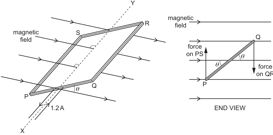
The coil has length QR of , width PQ of and has 190 turns of wire.
The plane of the coil is at an angle to a uniform magnetic field of flux density .
The axis XY of the coil is normal to the field.
The current in the coil is .
Working
Force on one side per turn:
Total force on side for turns:
Answer
6.4 × 10^-2 N
Background Concept
A straight current-carrying conductor of length in a magnetic field of flux density experiences a magnetic force
where is the current and is the angle between the direction of the current and the magnetic field. The force is maximum when the conductor is perpendicular to the field ().
For a coil with turns, each turn experiences the same force (in a uniform field), so the total force on one side of the coil is multiplied by .
Understanding the Question
We are asked for the magnitude of the force on side of a rectangular coil.
Given:
- length
- number of turns
From the diagram/setup, side is perpendicular to the magnetic field, so .
Approach
- Convert the side length into metres.
- Use for one turn.
- Multiply by turns to get the force on that side of the whole coil.
Step-by-Step Reasoning
Convert length:
For one turn on side (with ):
Compute:
Now multiply by turns:
Key Takeaways
- Use for a straight conductor in a magnetic field.
- For a multi-turn coil in a uniform field, total force on a side scales as .
- Always convert centimetres to metres before substituting.
Common Mistakes
- Forgetting to multiply by turns.
- Using the wrong side length (e.g. instead of ).
- Leaving in cm, causing an answer off by a factor of .
Things to Be Careful About
- The factor: check whether the conductor is perpendicular to the field. Here it is, so .
- Significant figures: the data are mostly 2 s.f., so is appropriate.
Working
The forces on sides and form a couple.
Perpendicular separation of the forces:
Torque of the couple:
Using from (a)(i):
Answer
τ = 1.6 × 10^-3 cosθ N m
Background Concept
A coil in a uniform magnetic field experiences forces on its opposite sides. If these forces are equal in magnitude, opposite in direction, and act along different parallel lines, they form a couple.
The moment (torque) of a couple is
where is the magnitude of one of the forces, and is the perpendicular distance between the lines of action of the two forces.
For a rectangular coil, the general result is
if is defined as the angle between the plane of the coil and the magnetic field (because the usual formula uses as the angle between the normal to the plane and , and ).
Understanding the Question
You have already found the force on side in part (a)(i). Now you must use that to show the torque is
The coil width is . The two forces act on the long sides ( and ) and produce a turning effect about axis .
Approach
- Treat the two magnetic forces as a couple.
- Find the perpendicular separation between the lines of action. Because the coil plane is tilted by , the separation perpendicular to the force is reduced by a factor .
- Use and substitute the value of from (a)(i).
Step-by-Step Reasoning
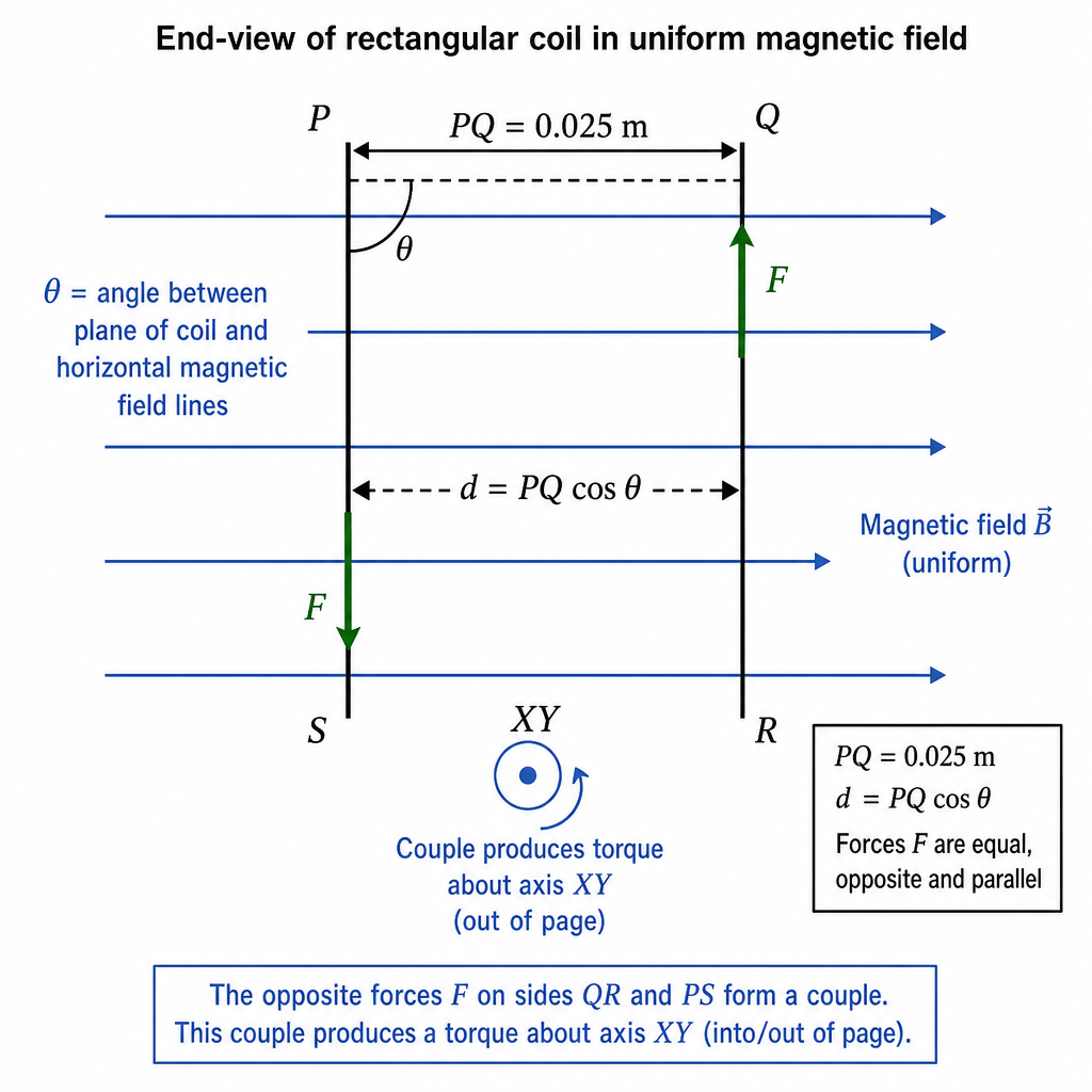
The forces on and are equal () and opposite, forming a couple.
The geometric separation between the sides is the coil width , but only the component perpendicular to the force contributes to the couple. From the end view, the perpendicular distance is
Torque is then
Using from (a)(i):
Multiply the numbers:
So
which is the required result.
Key Takeaways
- Two equal and opposite forces on different lines of action produce a couple.
- Torque of a couple is where is the perpendicular separation.
- The comes from geometry because is the angle between the plane of the coil and the field.
Common Mistakes
- Using instead of (mixing up whether is to the plane or to the normal).
- Using instead of .
- Forgetting to convert to .
Things to Be Careful About
- Always use the perpendicular distance between the forces, not the direct distance between the sides.
- Keep units consistent: in N, distance in m, so in N m.
Using the expression in (a)(ii) sketch, on the axes of Fig. 6.2, a graph to show the variation of the torque with angle for values of between and . Label the axis with an appropriate scale.
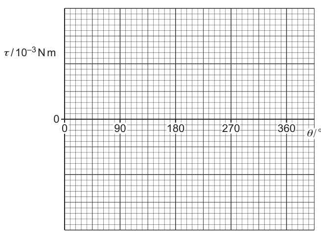
Answer
Using
the graph is a cosine curve with amplitude :
- : (maximum)
- :
- : (minimum)
- :
- :
Label the vertical axis (in units of ) to at least .
Cosine curve from +1.6×10^-3 at 0° to 0 at 90°, −1.6×10^-3 at 180°, 0 at 270°, back to +1.6×10^-3 at 360° (τ-axis scaled to ±1.6×10^-3 N m).
Background Concept
When a quantity depends on , its graph against (in degrees) has the cosine shape:
- maximum at ,
- crosses zero at ,
- minimum at ,
- crosses zero at ,
- returns to maximum at .
The amplitude is the coefficient in front of .
Understanding the Question
You are told the torque is
and must sketch against for to . The axes already show the key angles, and the -axis label is , so values should be plotted in multiples of .
Approach
- Identify the amplitude: .
- Calculate/recall cosine values at .
- Plot those points and draw a smooth cosine curve through them.
- Choose a vertical scale that clearly includes and on the provided axis units.
Step-by-Step Reasoning
Evaluate at standard angles:
On the axis labelled these correspond to .
Then sketch a smooth cosine curve through these points.
Key Takeaways
- A cosine relationship produces one full cycle between and .
- The coefficient sets the amplitude (maximum magnitude).
- Use the axis label carefully: means you plot numbers like , not .
Common Mistakes
- Drawing a sine curve (starting at zero) instead of a cosine curve (starting at maximum).
- Getting the sign wrong at .
- Using an unsuitable -axis scale that does not reach .
Things to Be Careful About
- Ensure the curve is smooth and symmetric about .
- The axis label implies a scaling; mark ticks clearly so the peak is at on that scaled axis.
The coil is now replaced by an identical coil wound on a ferrous core.
Suggest, with a reason, how the torque on this coil compares with the torque on the original coil.
Answer
The torque is larger with the ferrous core.
Reason: the core increases the magnetic flux density (higher permeability concentrates the field), and
Torque increases because the ferrous core increases flux density B (higher permeability), and τ ∝ B.
Background Concept
For a current-carrying coil in a magnetic field, the maximum torque is
For a given coil (, , fixed) and a given angle , the torque is directly proportional to the magnetic flux density .
A ferrous (iron/steel) core has high relative permeability. It provides an easier path for magnetic field lines and can concentrate the magnetic field inside/through the coil, increasing the flux density experienced by the conductors.
Understanding the Question
The original coil is air-cored. It is replaced by an identical coil, but wound on a ferrous core. Nothing else is stated to change (same dimensions, turns, current, external field arrangement). You must compare torques and give a reason.
Approach
Use the proportionality and consider what a ferrous core does to the magnetic field/flux density threading the coil.
Step-by-Step Reasoning
- In the torque expression, , , and are unchanged (identical coil).
- A ferrous core increases the effective magnetic flux density within the coil region because its high permeability concentrates magnetic field lines.
- Therefore, with a larger , the torque is larger for the same .
Key Takeaways
- Torque on a coil depends linearly on .
- Ferrous cores increase flux density due to high permeability (field lines preferentially pass through the core).
Common Mistakes
- Saying the torque decreases because the core is heavier (mass is not in the torque formula here).
- Claiming torque is unchanged because the external field is “uniform” (the core can still increase local in the coil).
Things to Be Careful About
- In real devices, cores can saturate at high fields; exam questions usually assume it increases without saturation unless stated otherwise.
- The comparison should be qualitative (“greater torque”) plus a physics reason tied to and permeability.
A bar magnet is suspended from a spring. One pole of the magnet oscillates freely in a coil of wire, as shown in Fig. 7.1.
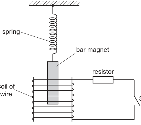
The switch S is initially open.
The switch S is now closed. As a result, the oscillations of the magnet are lightly damped.
Answer
Damping is the loss of energy from an oscillating system to the surroundings, causing the amplitude of oscillation to decrease with time.
Loss of energy from the oscillator to the surroundings so the amplitude decreases with time.
Background Concept
In oscillations, the system has mechanical energy that continually swaps between kinetic energy and potential energy. In an ideal (undamped) oscillator there is no energy loss, so the total energy stays constant and the amplitude stays constant.
Damping means there is a resistive effect (often a force opposite to the motion) that transfers energy out of the oscillating system into the surroundings. Because the total oscillation energy decreases, the amplitude decreases.
Understanding the Question
A bar magnet is hanging on a spring and oscillating up and down. The question asks for the meaning of “damping” in this context: what changes in the motion and what causes that change (in general terms).
Approach
State damping in terms of:
- energy being dissipated from the oscillating system, and
- a consequence that is easy to observe: amplitude reduces with time.
Step-by-Step Reasoning
- If energy is removed from the oscillation each cycle, the maximum kinetic energy and maximum potential energy become smaller.
- Maximum kinetic/potential energy in SHM is proportional to amplitude squared, so reduced energy means reduced amplitude.
- Therefore damping is described as energy loss that causes amplitude to decrease with time.
Key Takeaways
- Damping = energy dissipation from an oscillator.
- Observable effect = amplitude decreases with time.
Common Mistakes
- Saying only “amplitude decreases” without mentioning energy loss (often loses a mark).
- Confusing damping with a change in frequency (frequency may change slightly, but that is not the definition).
Things to Be Careful About
- The definition is about energy transfer out of the system; “friction” is just one possible cause.
- Damping does not necessarily stop oscillations immediately; it depends on whether damping is light/heavy.
Answer
The magnet continues to oscillate for many cycles and the amplitude decreases only slowly (successive peaks reduce gradually).
Oscillations persist for many cycles with amplitude decreasing only slowly.
Background Concept
“Light damping” means the resistive energy loss per cycle is small compared with the energy stored in the oscillation. The motion is still oscillatory, but the amplitude decays gradually.
In contrast:
- heavy damping removes energy so quickly that oscillations may die out within about one cycle or not occur at all,
- critical damping returns to equilibrium as quickly as possible without oscillating.
Understanding the Question
When the switch is closed, the oscillations become lightly damped. The question asks what you would see that tells you damping is light (not heavy/critical).
Approach
Describe the key visual feature of light damping: oscillations continue, and the envelope of the amplitude shrinks slowly over time.
Step-by-Step Reasoning
- Observe successive maximum displacements above/below equilibrium.
- In light damping, each maximum is only slightly smaller than the previous one.
- The magnet still crosses the equilibrium position repeatedly (many oscillations occur) before coming to rest.
Key Takeaways
- Light damping: “still oscillates” + “amplitude decreases slowly”.
Common Mistakes
- Saying only “amplitude decreases” without indicating it is slow/over many cycles.
- Saying the motion returns to equilibrium without oscillation (that describes critical/heavy damping).
Things to Be Careful About
- You do not need a numerical description; just a clear qualitative observation.
- The period is usually almost unchanged for light damping, but this is not the main indicator.
By reference to electromagnetic induction and to conservation of energy, explain why the oscillations are damped.
Answer
As the magnet moves in the coil, the magnetic flux linkage through the coil changes, so an emf is induced and a current flows in the closed circuit.
The induced current produces a magnetic field that opposes the change causing it (Lenz’s law), giving a force opposing the motion of the magnet.
Work is done against this opposing force; the magnet’s mechanical energy is transferred to electrical energy and is dissipated as thermal energy in the resistor, so the oscillation energy (and hence amplitude) decreases with time.
Changing flux induces an emf and current; the induced field opposes the motion (Lenz), doing negative work, so mechanical energy is dissipated as heat in the resistor and the amplitude decreases.
Background Concept
Electromagnetic induction occurs when the magnetic flux linkage through a coil changes:
- is the induced emf.
- The minus sign is Lenz’s law: the induced effect opposes the change that produces it.
If the circuit is closed, the induced emf drives a current . That current in the coil produces its own magnetic field, which can exert a force on the moving magnet. This force typically acts like a resistive (opposing) force, so it removes mechanical energy from the oscillation.
By conservation of energy, the “lost” mechanical energy is not destroyed: it becomes electrical energy in the circuit and is finally dissipated as thermal energy (mainly in the resistor) at a rate .
Understanding the Question
With the switch open, the coil circuit is incomplete, so any induced emf cannot drive a sustained current (and the electromagnetic braking effect is very small).
When the switch is closed, the magnet continues to oscillate through the coil, but now the oscillations are damped. The question asks you to explain this damping specifically using:
- electromagnetic induction (why current flows and what it does), and
- conservation of energy (where the oscillation energy goes).
Approach
- Argue that the moving magnet changes the magnetic flux linkage through the coil, so an induced emf appears (Faraday’s law).
- Since the circuit is now closed, an induced current flows.
- Use Lenz’s law to state that the induced current’s magnetic field opposes the motion / opposes the change in flux, producing a force opposite to the magnet’s velocity (magnetic braking).
- Conclude that work is done against this opposing force, so mechanical energy is converted into electrical energy and then into heat in the resistor, reducing amplitude.
Step-by-Step Reasoning
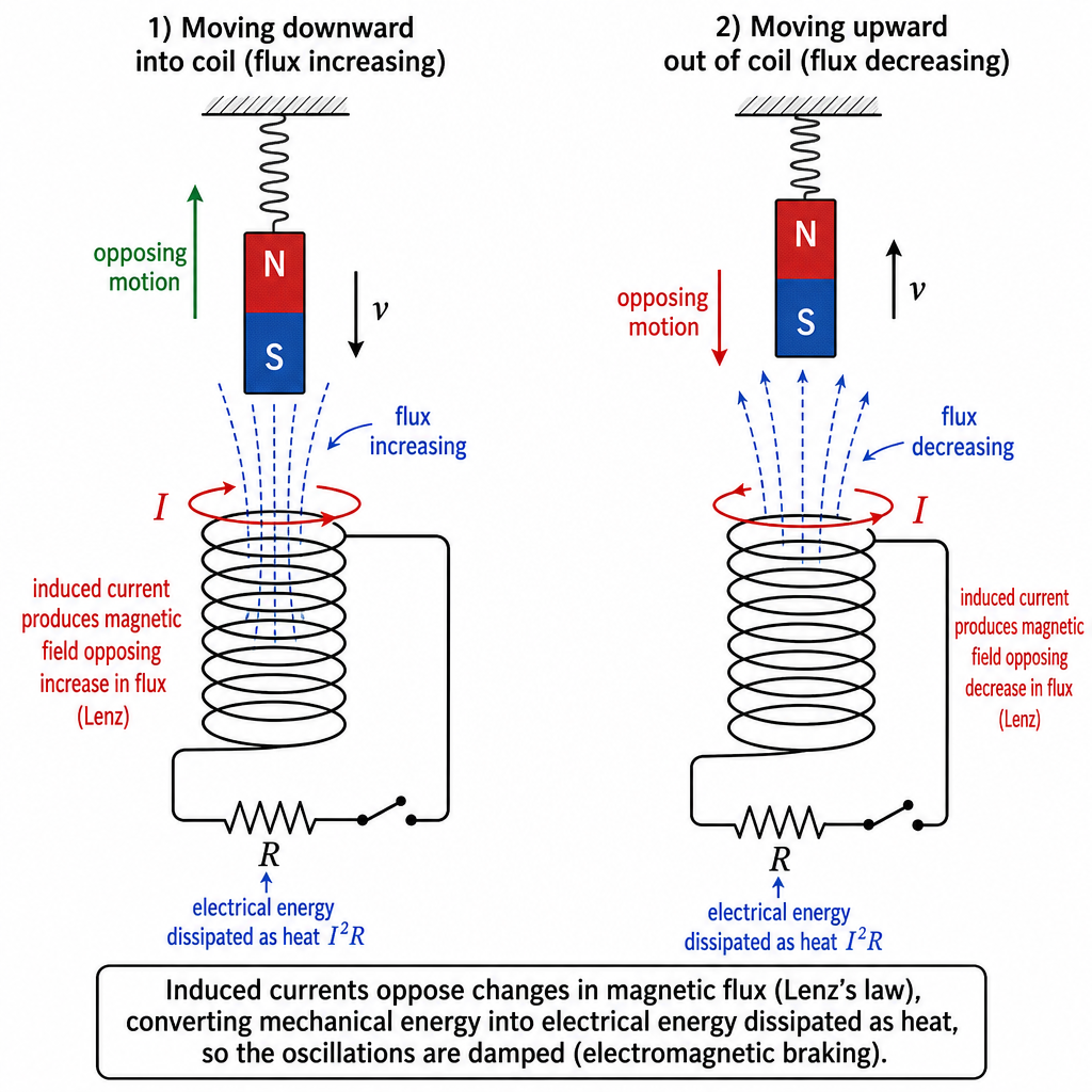
- As the magnet oscillates, it moves into and out of the coil. The magnetic field pattern from the magnet threads the turns of the coil.
- When the magnet’s position changes, the flux through the coil changes, so changes.
- Therefore an emf is induced in the coil.
- With switch closed, the circuit is complete, so the induced emf drives a current .
- The current produces a magnetic field of the coil. By Lenz’s law, this induced field is in the direction that opposes the change in flux:
- if the magnet is moving further into the coil (flux increasing), the coil produces a field that opposes the magnet approaching,
- if the magnet is moving out (flux decreasing), the coil produces a field that tends to keep the flux from decreasing (again opposing the motion).
- In both cases, the net effect is a force opposite to the magnet’s velocity, like a damping force.
- Because there is a force opposing motion, the magnet must do work against it each cycle. That work comes from the oscillation’s mechanical energy.
- The energy is transferred into the circuit as electrical energy and is dissipated as thermal energy in the resistor (and coil) due to Joule heating.
- Hence the total mechanical energy decreases, so the amplitude of oscillation decreases with time (damping).
Key Takeaways
- Motion of magnet in coil changing flux induced emf.
- Closed circuit induced current.
- Lenz’s law induced magnetic effect opposes motion (magnetic braking).
- Energy conservation mechanical energy becomes heat in the resistor, so amplitude decays.
Common Mistakes
- Mentioning “emf induced” but not stating that a current flows only because the switch is closed.
- Forgetting Lenz’s law (must state the induced effect opposes the change / opposes the motion).
- Saying energy is “lost” without stating it is dissipated as thermal energy in the resistor.
- Claiming the induced current “helps” the motion (wrong direction).
Things to Be Careful About
- The key is opposition to the change in flux; in an oscillation the direction reverses, so the induced current reverses too, but the force remains opposing the motion.
- Do not confuse the induced current with a permanent current source; it only exists while flux is changing.
- Energy transfer must be consistent with conservation of energy: mechanical energy decreases, thermal energy increases.
The procedure in (a) is repeated after replacing the resistor with one of greater resistance.
Suggest, with a reason, the effect of this change on the oscillations.
Answer
Greater resistance gives a smaller induced current (for the same induced emf), so the induced magnetic field and opposing force are smaller.
Therefore the damping is reduced: the magnet oscillates for longer and the amplitude decreases more slowly.
Damping decreases; amplitude falls more slowly / oscillations last longer because higher gives smaller induced current and weaker opposing magnetic force.
Background Concept
When a magnet oscillates in a coil, an induced emf is produced by the changing flux linkage. In a closed circuit, the induced current is approximately
where is the total resistance of the circuit.
The induced current produces a magnetic field that opposes the motion (Lenz’s law). The strength of this opposing effect depends on how large the induced current is. Also, the rate at which energy is dissipated as heat is
So changing changes the current and therefore the damping strength.
Understanding the Question
The only change from part (a) is that the resistor has been replaced by one with a greater resistance. You are asked to suggest what happens to the oscillations and give a reason.
Approach
- Use to decide how current changes when increases.
- Link smaller to a weaker induced magnetic field and hence a weaker opposing (damping) force.
- Conclude how the observable oscillations change (amplitude decay rate).
Step-by-Step Reasoning
- For the same magnet motion, the change of flux linkage with time is similar, so the induced emf is of similar size.
- Increasing the resistance increases , so the induced current decreases because .
- A smaller current produces a weaker magnetic field from the coil, so the magnetic braking force opposing the magnet’s motion is smaller.
- With a smaller opposing force, less mechanical energy is transferred out of the oscillation per cycle.
- Therefore the oscillations are less damped: the amplitude decreases more slowly and the magnet continues oscillating for more cycles.
Key Takeaways
- Larger in the external circuit generally reduces induced current.
- Reduced induced current reduces the Lenz-law opposing effect, so damping is smaller.
Common Mistakes
- Stating “greater resistance means greater damping” without considering that the current becomes smaller.
- Mixing up the ideas of emf and current: emf depends mainly on rate of change of flux, not on resistance.
Things to Be Careful About
- The question asks for a qualitative effect (more/less damping) and a reason; a full numerical treatment is not needed.
- Don’t claim the oscillation necessarily stops instantly; the key change is the rate of amplitude decay.
An incomplete circuit diagram of a bridge rectifier is shown in Fig. 8.1.
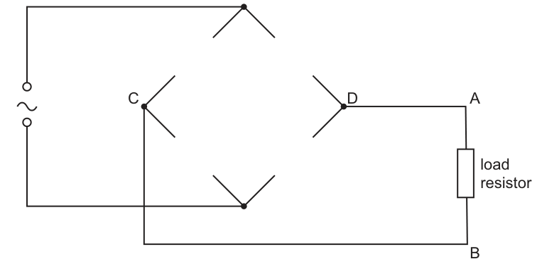
Complete Fig. 8.1 for the bridge rectifier such that the point A is at a positive potential with respect to point B.
Answer
Arrange the diodes so that:
- the two diodes connected to point have their cathodes at (anodes at the two a.c. input terminals),
- the two diodes connected to point have their anodes at (cathodes at the two a.c. input terminals),
so that current through the load is from to for both half-cycles.
Diodes oriented with both cathodes meeting at C (A) and both anodes meeting at D (B).
Background Concept
A bridge rectifier uses four diodes to make the current through a load flow in the same direction for both halves of an a.c. input cycle.
A diode conducts only when forward biased (anode at higher potential than cathode). In a bridge, two diodes conduct on each half-cycle, steering current so that the same output terminal is always at higher potential.
Understanding the Question
You are given a diamond-shaped bridge with two opposite corners connected to the a.c. supply. The other two corners are labelled and , and the load resistor is connected between and where is connected to and is connected to .
You must add diode symbols (with correct orientation) so that is always at a higher potential than , i.e. is the positive output terminal and is the negative output terminal.
Approach
Check each half-cycle separately:
- Assume the left a.c. input terminal is positive relative to the right. Choose two diodes that will conduct so current goes through the load from to .
- Then swap polarity (right positive relative to left). Choose the other pair of diodes that will conduct, again making current through the load go from to .
- The diode orientations must satisfy both conduction paths.
Step-by-Step Reasoning
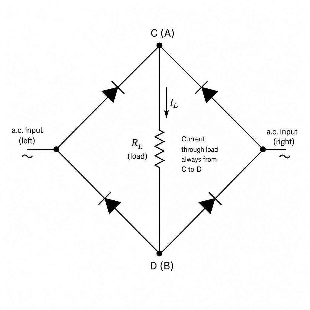
- Half-cycle 1: left a.c. terminal positive.
- We want current to go: left a.c. terminal load right a.c. terminal.
- So the diode from left a.c. terminal to must conduct when left is positive: anode at left, cathode at .
- The diode from to right a.c. terminal must conduct for current to leave toward the right terminal: anode at , cathode at right.
- Half-cycle 2: right a.c. terminal positive.
- We want current to go: right a.c. terminal load left a.c. terminal.
- So the diode from right a.c. terminal to must have anode at right, cathode at .
- The diode from to left a.c. terminal must have anode at , cathode at left.
- Combining these requirements:
- Both diodes connected to must have their cathodes at .
- Both diodes connected to must have their anodes at .
This ensures (and hence ) is always the positive output.
Key Takeaways
- In a bridge rectifier, two diodes conduct per half-cycle.
- To make the positive output, arrange the diodes so current is always delivered into and always leaves from .
Common Mistakes
- Reversing one diode so that one half-cycle gives the correct polarity but the other half-cycle gives positive.
- Placing both anodes at (this makes tend to become the negative output instead).
Things to Be Careful About
- Always label anode/cathode consistently: current enters the diode at the anode and leaves at the cathode (when forward biased).
- The required condition is about potential polarity ( positive relative to ), equivalently current direction through the load.
The variation with time of the potential difference (p.d.) across the load resistor is shown in Fig. 8.2.
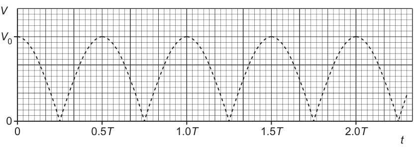
A capacitor is now connected between points C and D of the bridge rectifier. This results in smoothing of the p.d. across the load resistor. The difference between the maximum and minimum values of the smoothed p.d. is of the peak p.d. .
On Fig. 8.2, draw a line to show the variation of the potential difference across the load resistor with time . Your line should extend from to .
Answer
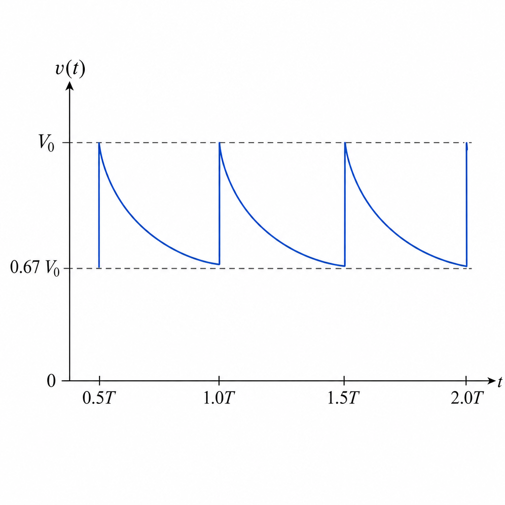
From to , draw a smoothing curve that:
- rises quickly to at each peak (),
- then decays approximately exponentially between peaks,
- reaching a minimum of about just before the next peak (since ).
Smoothed ripple: quick charge to V0 at each peak, exponential decay to about 0.67V0 before the next peak, repeating every 0.5T.
Background Concept
With a capacitor connected across the output of a rectifier, the capacitor charges up when the rectified p.d. increases (diodes conduct) and then discharges through the load resistor when the rectified p.d. falls (diodes stop conducting). This reduces the variation (ripple) of the output.
- Charging: fast (small effective resistance through conducting diodes / source), so the voltage rises quickly to near the peak.
- Discharging: slower, through the load resistor , following an exponential decay:
where .
For a full-wave rectified output, peaks occur every (twice the mains frequency), so the discharge time between recharge events is about .
Understanding the Question
Fig. 8.2 shows the full-wave rectified waveform across the load (no smoothing): repeated positive half-sine pulses with peak .
A capacitor is added across points and (i.e. across the load). You are told the ripple size is:
You must sketch the new (smoothed) output from to .
Approach
- Identify the times of the peaks on the existing rectified waveform (every ).
- At each peak, show the capacitor charging quickly to approximately .
- Between peaks, show exponential discharge through the load down to .
- Use the given ripple fraction to place relative to .
Step-by-Step Reasoning
- Take (the capacitor charges to the peak).
- Then
- On the sketch:
- At the curve should be at .
- From to draw a smooth exponential-like decay down to about .
- At show a rapid rise back up to .
- Repeat the same pattern from to and from to .
Key Takeaways
- A smoothing capacitor charges near the peak and discharges between peaks.
- Full-wave rectification halves the time between peaks to , improving smoothing.
- Ripple size determines how far the discharge curve falls before the next recharge.
Common Mistakes
- Drawing a straight-line discharge instead of a curved exponential decay.
- Using a discharge interval of instead of for a full-wave rectified output.
- Making the smoothed waveform drop below zero (it remains positive here).
Things to Be Careful About
- The ripple is given as a fraction of , not as a fraction of the mean output.
- The curve should touch (or almost touch) at each peak time and only fall to before the next peak.
Use your line in (b)(i) to determine, in terms of , the time constant of the smoothing circuit.
time constant = ______
Working
For full-wave rectification, time between peaks is .
Ripple: , with so .
Capacitor discharge:
Answer
1.25T
Background Concept
When the rectified input drops below the capacitor voltage, the diodes stop conducting and the capacitor discharges through the load resistance . The voltage across a discharging capacitor follows
where is the time constant (time to fall to of its initial value).
In a full-wave rectifier, the output peaks occur twice per input cycle, so the time between charging peaks is .
Understanding the Question
You have drawn (or are meant to draw) a smoothed waveform where the capacitor charges to about the peak value and then discharges to a minimum before the next peak.
You are told that the ripple amplitude (difference between maximum and minimum smoothed p.d.) is of . You must use this to find the time constant in units of .
Approach
- Convert “ of ” into a ratio .
- Use the exponential discharge over the time between peaks () to relate that ratio to .
- Rearrange using a natural logarithm.
Step-by-Step Reasoning
- If the capacitor charges to the peak, then .
Given
so
Hence
- For full-wave rectification, the capacitor is recharged every half-cycle, so the discharge time is
- Apply the discharge equation from down to :
Divide by :
- Take natural logs:
So
Key Takeaways
- Smoothing uses exponential discharge between successive peaks.
- For a bridge (full-wave) rectifier, the relevant discharge time is .
- A ripple percentage lets you find , which directly gives via logs.
Common Mistakes
- Using instead of (this would roughly double the value of ).
- Using as instead of recognising it is the difference.
- Forgetting the negative sign when taking of a number less than 1.
Things to Be Careful About
- The approximation is standard for these questions (diode drop ignored).
- Use (natural logarithm), not .
- Keep symbolic until the end so the final answer is directly in multiples of .
The resistance of the load resistor is now increased. The capacitance of the capacitor is unchanged.
State and explain the effect of this change on the smoothed output p.d.
Answer
Increasing the load resistance increases the time constant .
So the capacitor discharges more slowly between peaks, giving less ripple (minimum p.d. closer to ) and a smoother / larger mean output p.d.
Ripple decreases; output is smoother (Vmin closer to V0) because increasing R increases \tau = RC so the capacitor discharges more slowly.
Background Concept
In a smoothing circuit, the capacitor discharges through the load resistance when the rectified input falls below the capacitor voltage. The discharge rate is set by the time constant
A larger means a slower exponential decay, so the voltage falls less in a given time.
Understanding the Question
Only the load resistance is changed (increased). The capacitance is unchanged. You are asked for the effect on the smoothed output p.d. and an explanation.
Approach
- Use to see how the time constant changes.
- Relate time constant to how much the capacitor voltage drops between peaks.
- Translate that into ripple size and smoothness of the output.
Step-by-Step Reasoning
- If increases and is constant, then
- Between successive peaks (time roughly for a full-wave rectifier), the capacitor voltage decays like
- With a larger , the factor is closer to 1 for the same , so the voltage drops by a smaller amount.
Therefore:
- increases (it does not fall as far before the next recharge),
- the ripple amplitude decreases,
- the output is smoother and its mean value is higher.
Key Takeaways
- Increasing increases .
- Larger means slower discharge, so the capacitor maintains the output voltage better between peaks.
Common Mistakes
- Stating that ripple increases when increases (it is the opposite).
- Talking about the capacitor charging slower: in smoothing, the key change is the discharge through the load.
Things to Be Careful About
- The smoothing capacitor is across the load, so the relevant resistance for discharge is the load (or effective load) resistance.
- Make sure you describe a physical effect (smaller ripple / higher minimum voltage), not just “time constant increases”.
Answer
Wave–particle duality is the idea that the same entity (e.g. an electron or photon) can show wave behaviour (e.g. interference/diffraction) and also particle behaviour (e.g. localised impacts / quantised energy transfer), depending on the experiment.
The same entity can exhibit both wave properties (e.g. diffraction/interference) and particle properties (localised impacts/quantised transfer), depending on the experiment.
Background Concept
In classical physics, waves and particles are distinct:
- Waves spread out and can superpose, producing interference and diffraction patterns.
- Particles are localised objects that transfer energy and momentum in discrete interactions and arrive as individual “hits”.
Quantum physics shows that microscopic objects (photons, electrons, neutrons, atoms) do not fit purely into one category.
Understanding the Question
You are asked to describe what is meant by wave–particle duality. For 2 marks, you typically need:
- a statement that the same entity can behave as a wave, and
- a statement that it can behave as a particle (often with an example of each).
Approach
Give a clear definition and support it with examples of the types of behaviour that are considered wave-like and particle-like.
Step-by-Step Reasoning
- State that a single quantum object (such as an electron) can show wave effects.
- Suitable wave effects are diffraction and interference.
- State that the same object can also show particle effects.
- Suitable particle effects are localised detection events (individual spots on a screen) and quantised interactions (e.g. photons transferring energy in packets).
- Mention that which behaviour is observed depends on the measurement/experiment.
Key Takeaways
- Wave–particle duality: one object, two kinds of behaviour.
- Wave behaviour: diffraction/interference.
- Particle behaviour: localised impacts/quantised exchanges.
Common Mistakes
- Saying only “electrons are waves” or only “electrons are particles” (needs both).
- Referring to two different objects (e.g. “light is a wave and electrons are particles”) instead of the same entity.
Things to Be Careful About
- Use examples that are unambiguously wave-like (diffraction/interference) and particle-like (localised hits/quantised transfer).
- Keep the statement general: “depending on the experiment/observation.”
State the relationship between the de Broglie wavelength of a particle and its momentum . State the meaning of any other symbols that you use.
Answer
where is the Planck constant and is the momentum of the particle.
where is the Planck constant and is the particle momentum.
Background Concept
De Broglie proposed that particles can have an associated wavelength (a matter wave). The de Broglie wavelength is linked to momentum by
where:
- is the de Broglie wavelength (in ),
- is the Planck constant (),
- is the momentum of the particle (in ).
For a non-relativistic particle, momentum is often .
Understanding the Question
The question asks you to state the relationship and then state the meaning of any other symbols used. So you must not only write the formula, but also identify what and represent.
Approach
Write the de Broglie equation and then define the symbols besides .
Step-by-Step Reasoning
- Recall the standard result:
- Define the symbols:
- : Planck constant.
- : momentum of the particle.
(You do not need to substitute unless asked.)
Key Takeaways
- Matter-wave wavelength decreases as momentum increases.
- Always define any extra symbols to secure the explanation marks.
Common Mistakes
- Writing (inverted).
- Forgetting to define or when explicitly asked.
Things to Be Careful About
- Use correct symbols: for wavelength, for momentum, for Planck constant.
- Do not confuse with (reduced Planck constant) unless the formula uses it explicitly.
A narrow beam of electrons, all with the same speed, is incident normally on a carbon film. The electrons then move on to a fluorescent screen, as illustrated in Fig. 9.1.
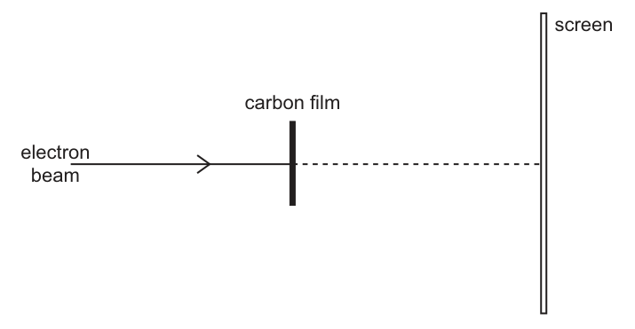
The apparatus is in a vacuum. The pattern produced on the screen is shown in Fig. 9.2.
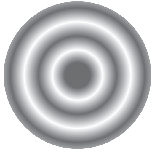
Explain why the pattern in Fig. 9.2 provides experimental evidence to indicate a wave nature for the electrons.
Answer
The concentric bright and dark rings are a diffraction / interference pattern. Diffraction (and the resulting constructive/destructive interference) is a wave effect, so the electrons must have a wave nature.
The rings are a diffraction/interference pattern (constructive and destructive interference), which is a wave effect, so electrons show wave nature.
Background Concept
A hallmark of waves is superposition: when waves overlap they interfere.
- Constructive interference gives maxima (bright regions).
- Destructive interference gives minima (dark regions).
When a wave passes through a thin crystal (or polycrystalline film), it can be scattered by regularly spaced атомs. The scattered waves can interfere, producing a pattern of maxima and minima. This is the basis of diffraction patterns (e.g. X-ray diffraction). If electrons produce the same kind of pattern, they must be behaving as waves.
Understanding the Question
Electrons of one speed strike a carbon film and then hit a fluorescent screen. The observed result is concentric bright and dark rings.
The question asks why this is evidence of a wave nature for electrons.
Approach
Identify what physical phenomenon creates rings (diffraction/interference), then state why that phenomenon is wave-specific.
Step-by-Step Reasoning
- A polycrystalline carbon film has many tiny crystallites with different orientations.
- Electron waves are scattered by atomic planes in many directions.
- For certain scattering angles, the path difference between waves scattered from successive planes satisfies a constructive condition (often described by Bragg-type reasoning), producing intensity maxima.
- Because many crystallite orientations are present, these maxima occur on cones of angle; when they hit a flat screen, they appear as rings.
- Since diffraction and interference require wave superposition, the ring pattern is direct experimental evidence that electrons have an associated wavelength.
Key Takeaways
- A pattern of alternating maxima/minima (bright/dark) indicates interference.
- Interference/diffraction is a defining property of waves.
- Therefore, electrons exhibit wave behaviour.
Common Mistakes
- Saying “electrons are waves because they make rings” without mentioning diffraction/interference.
- Claiming the pattern is due to electrostatic or magnetic deflection (those typically shift the whole beam rather than create multiple maxima/minima).
Things to Be Careful About
- Use the correct wave terminology: diffraction/interference, constructive/destructive.
- The vacuum is important experimentally (reduces collisions), but the main evidence comes from the diffraction pattern itself, not from the vacuum.
The speed of the electrons is increased.
Suggest, with a reason, how this change affects the pattern observed on the screen.
Working
Increasing speed increases momentum .
So increases decreases.
Smaller gives smaller diffraction angles, so the ring radii (and ring spacing) on the screen decrease.
Answer
The rings move closer to the centre / become smaller (reduced spacing) because the de Broglie wavelength decreases when the electron speed increases.
Ring radii (and spacing) decrease: higher speed → larger momentum → smaller de Broglie wavelength → smaller diffraction angle.
Background Concept
For electrons,
So when momentum increases, wavelength decreases.
Diffraction angles depend on wavelength: for a fixed spacing in the scattering structure (atomic spacing in the carbon), a smaller wavelength produces smaller diffraction angles. Geometrically, on a screen at distance , the ring radius is related to the scattering angle approximately by for small angles. So smaller means smaller .
Understanding the Question
The electron beam and carbon film produce a ring diffraction pattern on a fluorescent screen. You increase the speed of the electrons and must predict what happens to the pattern and give a reason.
Approach
- Link speed increase to momentum increase.
- Use de Broglie to deduce wavelength decrease.
- Use the idea “smaller wavelength → less diffraction (smaller angles)” to predict the ring pattern change.
Step-by-Step Reasoning
- Increasing electron speed increases momentum (non-relativistically ).
- From de Broglie:
so increasing makes smaller.
- Diffraction/interference conditions in the carbon film depend on wavelength; smaller corresponds to smaller scattering angle for maxima.
- On the screen, each diffraction angle maps to a ring radius.
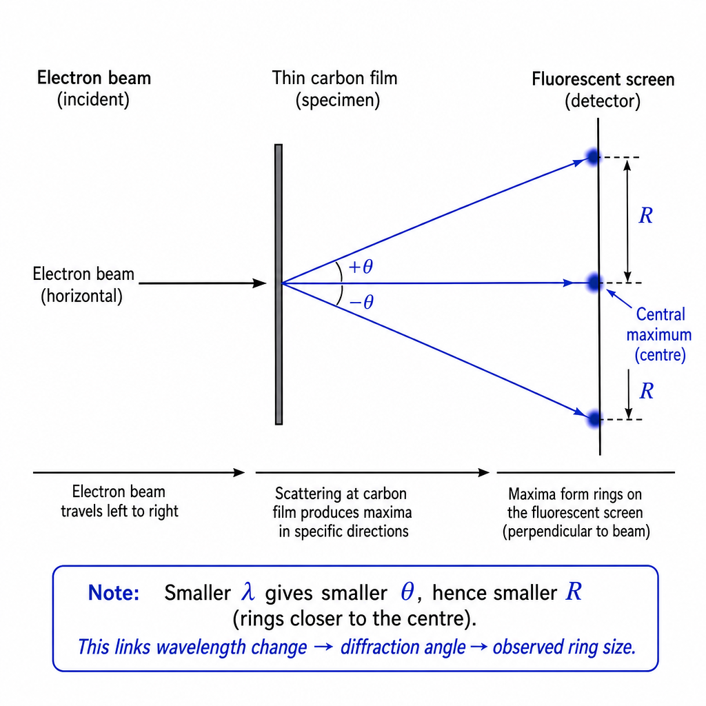
- Therefore the rings contract: smaller ring diameters (and typically rings are closer together).
Key Takeaways
- Speed up electrons → momentum increases → de Broglie wavelength decreases.
- Smaller wavelength → reduced diffraction angles → smaller ring radii on the screen.
Common Mistakes
- Predicting the rings spread out when speed increases (it is the opposite).
- Forgetting the reason must explicitly mention de Broglie wavelength or momentum.
Things to Be Careful About
- State the chain clearly: .
- If you mention “less diffraction”, translate it into what is seen: rings move inward / radii decrease.
Describe how the piezoelectric crystal in a transducer generates ultrasound waves for use in medical diagnosis.
Answer
- An alternating p.d. is applied across the piezoelectric crystal.
- The crystal repeatedly expands and contracts (changes thickness) at the same frequency.
- This makes the face of the transducer vibrate and produce longitudinal pressure variations in the adjacent medium, i.e. ultrasound waves.
An a.c. p.d. across the piezoelectric crystal makes it alternately expand/contract, so the transducer face vibrates at the driving frequency and generates longitudinal pressure waves (ultrasound) in the medium.
Background Concept
The piezoelectric effect is the coupling between электрical and mechanical behaviour in certain crystals.
- Direct effect: mechanical stress on the crystal produces a charge separation and hence a p.d.
- Inverse effect: an applied p.d. produces a change in the crystal dimensions.
In an ultrasound transducer used for imaging, we use the inverse piezoelectric effect to generate ultrasound. If the crystal face vibrates, it pushes and pulls on the material in contact with it, creating longitudinal pressure variations that propagate as an ultrasound wave.
Understanding the Question
The question asks specifically how the piezoelectric crystal generates ultrasound for diagnosis (so: electrical drive (\rightarrow) crystal vibration (\rightarrow) ultrasound in tissue/coupling gel). The key ideas needed are:
- apply an alternating voltage,
- the crystal changes shape periodically,
- those vibrations launch a longitudinal wave.
Approach
State the cause-and-effect chain that creates a sound wave:
- apply an a.c. (or rapid pulses) p.d. to the crystal,
- inverse piezoelectric effect makes the crystal expand/contract,
- the oscillating face drives the medium, creating pressure oscillations (ultrasound).
Step-by-Step Reasoning
- Alternating voltage applied: The transducer electronics apply an alternating p.d. (often as short pulses) across electrodes on the crystal.
- Crystal deforms: Because it is piezoelectric, the applied electric field causes the crystal lattice to distort. When the p.d. reverses, the distortion reverses, so the crystal repeatedly increases and decreases in thickness.
- Vibrations produce ultrasound: The front face of the crystal is in contact with a coupling medium (gel) and then tissue. As the face moves back and forth, it creates alternating compressions and rarefactions in the medium. These propagate away as a longitudinal wave at ultrasound frequency.
(Extra context: the transducer is often designed so the driving frequency matches a mechanical resonance of the crystal to increase amplitude, but the question only requires the basic generation mechanism.)
Key Takeaways
- Ultrasound is produced by mechanical vibration of a surface.
- A piezoelectric crystal converts an alternating electrical signal into alternating mechanical deformation.
- The oscillation launches longitudinal pressure waves in the contacting medium.
Common Mistakes
- Describing the direct piezoelectric effect (pressure (\rightarrow) voltage) instead of generation (voltage (\rightarrow) vibration).
- Saying the wave is transverse (ultrasound in tissue is longitudinal).
- Forgetting that it is the alternating nature of the applied p.d. that produces continuous oscillation.
Things to Be Careful About
- Use correct language: “expand/contract”, “vibrate/oscillate”, “compressions/rarefactions”.
- The ultrasound frequency is the same as the driving frequency (or pulse repetition determines bursts), so make that link explicitly if needed.
A parallel ultrasound beam is incident on the boundary between two media, as illustrated in Fig. 10.1.
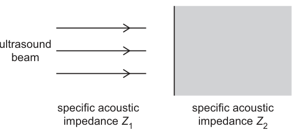
The media have specific acoustic impedances and .
At the boundary, a fraction of the incident intensity of the ultrasound beam is reflected. The remainder is transmitted.
Answer
Specific acoustic impedance of a medium is the ratio of acoustic pressure to particle velocity in the wave:
and for a plane wave
Specific acoustic impedance is the ratio of acoustic pressure to particle velocity (for a plane wave, Z = ρc).
Background Concept
For a travelling plane sound wave, particles of the medium oscillate back and forth while the wave carries energy forward. Two useful wave quantities are:
- acoustic pressure (pressure variation) (p) (units (\text{Pa})),
- particle velocity (u) (units (\text{m s}^{-1})).
The specific acoustic impedance (Z) describes how “hard” it is for the wave to make the particles move:
For a plane wave in a uniform medium, it can also be shown that
where (\rho) is density and (c) is wave speed in that medium. Unit check: (\rho c) has units (\text{kg m}^{-3} \times \text{m s}^{-1} = \text{kg m}^{-2} \text{s}^{-1}), which is equivalent to (\text{Pa s m}^{-1}).
Understanding the Question
You are asked to state what is meant by specific acoustic impedance, so you need a clear definition (usually ratio form), and an accepted equivalent expression (often (\rho c)).
Approach
Give the definition and, if possible, the common plane-wave relation:
- definition: (Z = p/u),
- relation to material properties: (Z = \rho c).
Step-by-Step Reasoning
- Start from the definition: impedance is a ratio of a “driving” quantity to a “response” quantity.
- In acoustics, the “drive” is the pressure variation (p) and the response is particle speed (u), hence (Z = p/u).
- For plane waves in a medium, pressure and particle speed are linked through the medium’s density and sound speed, giving (Z = \rho c).
Key Takeaways
- (Z) measures opposition of a medium to particle motion in a sound wave.
- (Z) can be defined by (Z = p/u) and (for plane waves) equals (\rho c).
Common Mistakes
- Confusing impedance with attenuation (they are different: impedance affects reflection/transmission at boundaries).
- Writing (Z = \rho / c) (wrong: it is (\rho c)).
- Missing the idea of it being a ratio of pressure to particle velocity.
Things to Be Careful About
- Use particle velocity (u), not wave speed (c), in the ratio definition.
- State clearly it is a property of the medium for plane waves (not of the source).
Answer
If then (no reflection).
As the difference between and increases, increases (greater fraction reflected), tending towards for a very large mismatch.
(For normal incidence:)
α is zero when Z1 = Z2 and increases as the mismatch |Z2 − Z1| increases, approaching 1 for a very large mismatch (α = ((Z2 − Z1)/(Z2 + Z1))^2 for normal incidence).
Background Concept
When a wave meets a boundary between two media, part of it can be reflected and part transmitted. The amount reflected depends on how well the two media “match” in terms of specific acoustic impedance (Z).
For normal (perpendicular) incidence, the intensity reflection coefficient (\alpha) is
This is a squared ratio, so (\alpha) is always between 0 and 1.
Understanding the Question
A parallel beam hits the boundary between media with impedances (Z_1) and (Z_2). You are asked to describe how the reflected fraction (\alpha) depends on the relative values of (Z_1) and (Z_2), so the key is “impedance mismatch”.
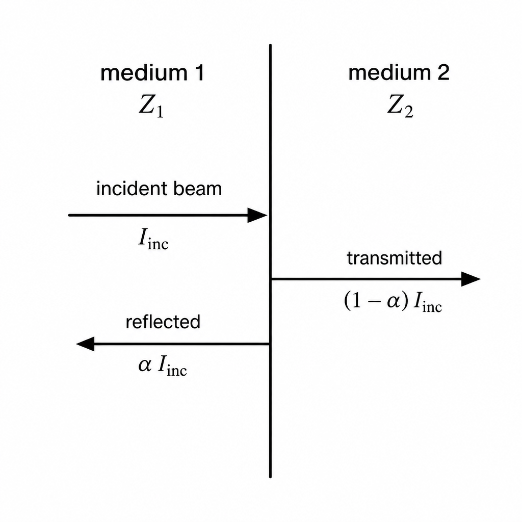
Approach
Use limiting cases and/or the standard formula:
- if impedances are equal, expect no reflection,
- larger mismatch gives more reflection,
- very large mismatch gives almost total reflection.
Step-by-Step Reasoning
- Start with the formula for normal incidence:
- Case (Z_1 = Z_2): numerator ((Z_2 - Z_1) = 0), so
meaning all intensity is transmitted (ideal matching).
-
As (|Z_2 - Z_1|) increases: the numerator grows relative to the denominator, so the fraction increases and hence (\alpha) increases.
-
Very large mismatch: if (Z_2 \gg Z_1), then
so (\alpha \to 1) (almost all intensity reflected). Similarly if (Z_1 \gg Z_2).
Key Takeaways
- Reflection at a boundary is controlled by impedance mismatch.
- (Z_1 = Z_2) gives no reflection.
- The larger the mismatch, the larger the reflected fraction, approaching 1 for an extreme mismatch.
Common Mistakes
- Saying reflection depends on the absolute size of (Z) rather than the difference between (Z_1) and (Z_2).
- Claiming (\alpha) could be greater than 1 (it cannot, it is a fraction of intensity).
- Forgetting that (\alpha) is the fraction of intensity, not amplitude.
Things to Be Careful About
- The question states a fraction of intensity, so the dependence is squared compared with many amplitude reflection formulas.
- Ensure you mention the special case (Z_1 = Z_2) explicitly; it is a common marking point.
A parallel ultrasound beam of intensity enters a region of soft tissue. After passing a distance of through this tissue, the intensity of the ultrasound is .
Calculate the linear attenuation coefficient of ultrasound in the soft tissue. Give a unit with your answer.
= ______ unit ______
Working
Use
Given and :
Answer
23 m^-1
Background Concept
As ultrasound travels through tissue, its intensity decreases because energy is absorbed and scattered. This is modelled by exponential attenuation:
where
- (I_0) is the intensity at the start of the material,
- (I) is the intensity after travelling distance (x),
- (\mu) is the linear attenuation coefficient.
The unit of (\mu) must be the inverse of distance (e.g. (\text{m}^{-1}) if (x) is in metres).
Understanding the Question
You are told that after travelling (2.1\ \text{cm}) in soft tissue, the intensity is (0.62 I_0). You must calculate (\mu) and state a suitable unit.
Known:
- (I/I_0 = 0.62)
- (x = 2.1\ \text{cm})
Unknown:
- (\mu)
Approach
- Start from (I = I_0 e^{-\mu x}).
- Divide by (I_0) to use the ratio (I/I_0).
- Take (\ln) to bring (\mu) out of the exponent.
- Convert (x) to SI units and compute (\mu).
Step-by-Step Reasoning
- Write the attenuation law and form a ratio:
- Substitute (I/I_0 = 0.62) and convert distance:
Using SI:
So
- Take natural logs:
- Rearrange for (\mu):
- Calculate: (\ln(0.62) \approx -0.478), so
Rounded appropriately:
Key Takeaways
- Intensity attenuation in tissue is exponential: (I = I_0 e^{-\mu x}).
- Taking (\ln) is the standard way to rearrange exponential decay.
- The unit of (\mu) is the inverse of the distance unit used for (x).
Common Mistakes
- Using base-10 log instead of natural log (must use (\ln) for (e^{-\mu x})).
- Forgetting to convert (2.1\ \text{cm}) to metres when giving (\mu) in (\text{m}^{-1}).
- Dropping the minus sign: since (\ln(0.62)) is negative, (\mu) must come out positive.
Things to Be Careful About
- Be consistent: if you keep (x) in cm, you must give (\mu) in (\text{cm}^{-1}). If you convert to metres, use (\text{m}^{-1}).
- Quote a sensible number of significant figures (matching the given data, typically 2 s.f. here).
The deuterium nucleus () has a mass defect of . The helium-4 nucleus () has a mass defect of . Helium-4 is formed from deuterium in a nuclear reaction that can be represented by the equation
Answer
Nuclear fusion.
Nuclear fusion.
Background Concept
In nuclear physics, reactions are often classified as:
- Fusion: two (or more) light nuclei combine to form a heavier nucleus.
- Fission: a heavy nucleus splits into two (or more) lighter nuclei.
In fusion, the final nucleus typically has a higher binding energy per nucleon than the initial nuclei, so energy is released.
Understanding the Question
The reaction given is:
This shows multiple light nuclei (deuterium nuclei) combining overall to produce a heavier nucleus (helium-4), along with individual nucleons.
Approach
Decide whether the overall process is combining to make a heavier nucleus (fusion) or splitting a heavier nucleus into lighter ones (fission).
Step-by-Step Reasoning
- The reactant nuclei are deuterium nuclei, which are light.
- A helium-4 nucleus is produced, which is heavier than deuterium.
- Therefore, the process is fusion.
Key Takeaways
- Fusion: light nuclei combine to form heavier nuclei.
- Fission: heavy nuclei split into lighter nuclei.
Common Mistakes
- Calling it fission because more particles appear on the right-hand side (the classification depends on the change in nuclear mass/combination, not the number of products).
Things to Be Careful About
- Use the overall change: light to heavier nucleus implies fusion, even if extra nucleons are emitted.
Show that the energy released when one nucleus of helium-4 is formed from deuterium is .
Working
Binding energy .
Initial total mass defect:
Final total mass defect (only the helium nucleus is bound):
Increase in mass defect:
Convert to energy ( , ):
Answer
.
3.47 × 10^−12 J
Background Concept
A mass defect for a nucleus is the difference between:
- the total mass of its separated nucleons, and
- the actual mass of the nucleus.
This “missing” mass corresponds to the binding energy of the nucleus:
If a reaction produces nuclei with a greater total binding energy than the reactants, the difference is released as energy.
Understanding the Question
You are given the mass defects:
- Deuterium nucleus:
- Helium-4 nucleus:
The reaction is:
A proton and a neutron on the product side are free nucleons, so they have no nuclear binding energy to include. The energy released is the increase in total binding energy from reactants to products.
Approach
- Convert each nucleus’s mass defect into a binding energy conceptually (you can keep everything in u until the end).
- Find the total mass defect (i.e. total binding) initially and finally.
- The energy released is:
- Convert u to kg and apply .
Step-by-Step Reasoning
1) Total initial binding (in u):
There are 3 deuterium nuclei, each with mass defect :
2) Total final binding (in u):
Only the helium-4 nucleus is bound:
3) Increase in binding (in u):
This increase corresponds to energy released.
4) Convert to joules:
Using ,
Then
Key Takeaways
- Mass defect corresponds to nuclear binding energy via .
- Energy released in a fusion reaction is the increase in total binding energy.
- Free protons/neutrons contribute no nuclear binding energy.
Common Mistakes
- Subtracting the wrong way round (using gives a negative value).
- Adding mass defects of the free proton and neutron (they are not bound nuclei).
- Forgetting to convert u to kg before using .
Things to Be Careful About
- Keep track of what the given “mass defect” represents: it is already the “missing mass” for that nucleus.
- Use consistent significant figures; the final value is typically quoted to 3 s.f. here.
- Ensure you use and square it correctly.
A star has a radius of . Helium-4 is produced in this star, from deuterium, at a mass rate of . All the energy released from this process is radiated away from the star. All the energy that is radiated from the star is released by this process.
Working
Energy released per helium nucleus formed (from (a)(ii)):
Mass of one helium-4 nucleus:
Number of helium nuclei formed per second:
Luminosity (energy per second):
Answer
.
3.83 × 10^26 W
Background Concept
Luminosity is the total energy emitted per unit time (power) by a star:
If each nuclear reaction releases energy and happens at a rate of reactions per second, then:
Here the reaction rate is not given directly, but the mass production rate of helium is given. If helium is produced at a mass rate , then
Understanding the Question
Given:
- Helium-4 is produced at mass rate .
- Energy released per helium-4 nucleus formed (from part a(ii)) is .
- All this energy is radiated away, and all radiated energy comes from this process, so luminosity equals nuclear power output.
We must find .
Approach
- Find the mass of one helium-4 nucleus (use as its mass).
- Convert the mass production rate into number of helium nuclei produced per second.
- Multiply by energy released per helium nucleus.
Step-by-Step Reasoning
1) Mass of one helium nucleus
Take approximately :
2) Number produced per second
3) Convert to luminosity (power)
The unit check is helpful: .
Key Takeaways
- Luminosity is power output.
- Use if you know the energy per reaction and the reaction rate.
- Convert a mass rate to a particle rate using .
Common Mistakes
- Using instead of .
- Forgetting that the mass rate refers to helium produced, not deuterium consumed.
- Using the mass defect (in u) directly as a mass of the nucleus.
Things to Be Careful About
- Keep powers of ten under control when dividing by .
- Use the energy per one helium nucleus formed, not per deuterium nucleus.
- Quote the final luminosity to appropriate significant figures (typically 3 s.f.).
Use your answer in (b)(i) to determine the surface temperature of the star.
temperature = ______
Working
Using Stefan–Boltzmann law:
With , , :
Answer
.
5.77 × 10^3 K
Background Concept
A star is often modelled as an (approximate) black body radiator. The Stefan–Boltzmann law relates its luminosity to its surface area and surface temperature :
where:
- is the star’s radius,
- is the Stefan–Boltzmann constant.
Understanding the Question
You are given the radius of the star and (from part (b)(i)) the luminosity. You must use Stefan–Boltzmann to find the surface temperature.
Given:
Find .
Approach
Rearrange the Stefan–Boltzmann law to make the subject:
Then substitute values in SI units and take the fourth root.
Step-by-Step Reasoning
Start with:
Rearrange:
Substitute:
The value is close to , comparable with the Sun’s surface temperature, which is a good plausibility check.
Key Takeaways
- Use for blackbody radiation from a spherical surface.
- Solve for by taking the fourth root.
- Keep units SI throughout.
Common Mistakes
- Forgetting the (using or instead).
- Using diameter instead of radius.
- Failing to take the fourth root (taking a square root instead).
Things to Be Careful About
- is very sensitive to errors because of the fourth root, but you must still keep powers of ten consistent.
- Ensure is used with correct units and value.
- Quote to 3 s.f. (or consistent with the precision of ).