Physics 9702/51 — October/November 2017
Cambridge A-Level · Planning, Analysis and Evaluation · worked solutions for every part, with the mark scheme
Topics Analysis, Conclusions and Evaluation · Planning
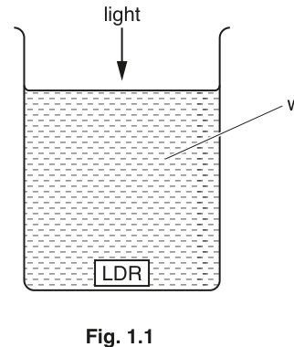
A student is investigating the resistance of a light-dependent resistor (LDR) separated from a source of light by different depths of water as shown in Fig. 1.1.
It is suggested that the relationship between the resistance of the LDR and the depth of the LDR in the water is
where is a constant.
Design a laboratory experiment to test the relationship between and . Explain how your results could be used to determine a value for . You should draw a diagram, on page 3, showing the arrangement of your equipment. In your account you should pay particular attention to
• the procedure to be followed,
• the measurements to be taken,
• the control of variables,
• the analysis of the data,
• any safety precautions to be taken.
Variables
- Independent variable: depth of LDR below the water surface, .
- Dependent variable: resistance of LDR, .
- Controls: lamp-to-water-surface distance, lamp supply (brightness), LDR orientation, type/amount/clarity of water, ambient light level, temperature.
Apparatus
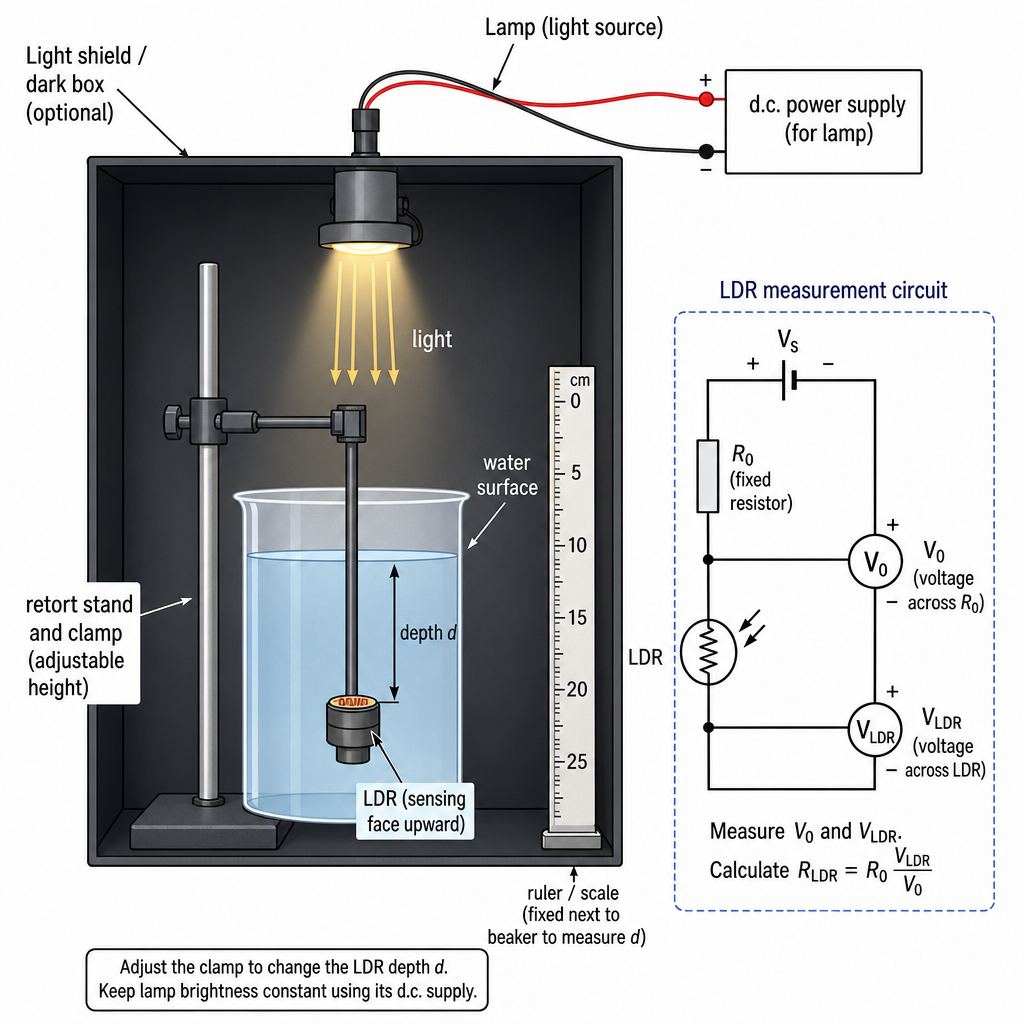
Lamp + d.c. power supply, transparent tank/beaker of water, LDR sealed in waterproof transparent bag/thin plastic film, retort stand/clamp to hold and move LDR vertically, metre rule (or scale fixed to tank), d.c. supply for circuit, fixed resistor , two digital voltmeters (or one moved), connecting leads.
Procedure and measurements
- Set the lamp at a fixed height above the water surface and keep it powered from a constant supply.
- Mount the LDR facing upwards directly beneath the lamp. Use the clamp and ruler to set the depth (distance from water surface to the sensitive surface of the LDR).
- Connect the LDR in series with a fixed resistor across a fixed d.c. supply (potential divider).
- For each chosen , measure:
- across the LDR,
- across (or measure current in series).
- Calculate the current
and hence
- Take at least 6 values of over a suitable range, repeat readings (e.g. 3 times) and average for each .
Control of variables
- Keep lamp height above the surface constant and keep lamp voltage/current constant.
- Reduce ambient light (dark room or light shield around apparatus).
- Keep water depth above the LDR equal to and keep alignment fixed (lamp, surface, LDR on one vertical line).
- Keep temperature approximately constant (allow lamp to warm up first; take readings quickly; stir water gently and wait for surface to settle).
- Use the same water and container throughout; avoid bubbles or droplets on the LDR covering.
Analysis and determination of
Given
so . For each reading calculate and plot a graph of (y-axis) against (x-axis).
Gradient is
so
A straight line through (approximately) the origin supports the suggested relationship.
Safety
- Keep electrical equipment and connections away from spilled water; dry hands before adjusting leads.
- Use low-voltage supplies.
- Ensure the lamp does not overheat the container; do not touch a hot bulb; keep lamp stable to prevent it falling into water.
See working
Background Concept
An LDR is a resistor whose resistance depends on the light intensity (illuminance) falling on it: higher light intensity usually gives lower resistance. Here, the LDR is placed under water, and as the depth increases, less light reaches it (due to absorption/scattering and spreading), so the resistance changes.
The suggested model is
This has the form with proportionality constant . A standard way to test such a relationship is to keep everything else constant, vary , measure , and check whether a graph of against is a straight line.
To determine , we use the idea that for a linear graph , the gradient can be measured and then rearranged to solve for the unknown constant.
Understanding the Question
You must design (plan) a workable experiment that:
- varies the depth of the LDR below the water surface,
- measures the resistance for each depth,
- controls other variables that affect LDR resistance (lamp brightness, ambient light, alignment, temperature, water clarity),
- analyses results in a way that tests the proposed equation,
- explains how the value of is obtained from the results,
- includes a labelled diagram of the set-up,
- states sensible safety precautions (water + electricity + hot lamp).
So the key deliverables are: method, measurements, controls, graph/analysis, and safety.
Approach
- Choose a reliable way to measure while the LDR is illuminated. In a planning question, a potential divider is a strong method because it avoids using an ohmmeter mode (which can be sensitive to contact issues and may be awkward while the LDR is in water).
- Vary systematically using a clamp and a ruler scale.
- For each , measure voltages and calculate using .
- Linearise: since , plot vs .
- Use gradient to calculate via .
- Build in control measures and repeats to reduce uncertainty.
Step-by-Step Reasoning
1) Circuit to obtain
Put the LDR in series with a known resistor across a fixed d.c. supply . This makes a potential divider. Measure the voltage across (call it ) and across the LDR (call it ).
Because is known, you can find the current in the series circuit:
Then the resistance of the LDR at that depth is:
This is direct use of Ohm's law and is valid because the same current flows through series components.
2) Varying and measuring it
Mount the LDR on a clamp so it can be moved vertically. Measure as the vertical distance from the water surface to the active face of the LDR. Use a ruler fixed to the tank, or measure from a reference mark.
Choose a range of at least 6 depths (more is better), spaced so that covers a good range (this improves the reliability of the gradient).
3) Controlling variables (why it matters)
The LDR resistance is affected by more than depth:
- Lamp brightness: must be constant, so use a stable power supply and do not move the lamp.
- Distance above water: keep lamp-to-surface distance constant so only changes.
- Alignment: keep the LDR directly under the lamp each time; otherwise changing the angle changes the intensity at the LDR.
- Ambient light: stray light adds to the illumination and changes ; use a shield/darkened area.
- Water clarity and bubbles: scattering/absorption changes with murkiness and bubbles; use the same clear water and remove bubbles.
- Temperature: resistances can drift with temperature; allow lamp to stabilise, take readings reasonably quickly, and keep conditions similar.
4) Analysis to test the relationship
From the model:
Let and . Then:
So if the relationship is correct:
- a plot of (y-axis) against (x-axis) should give a straight line,
- the intercept should be close to zero (within experimental uncertainty).
5) Determining from the graph
The gradient is
so
You would calculate from a large triangle on the best-fit line. If the question expects uncertainty discussion, you could repeat readings and/or draw worst acceptable lines to estimate an uncertainty in , then propagate it to (since , the percentage uncertainty in is approximately the same as that in ).
6) Safety
The main hazards are water near electrical equipment and a hot lamp. Control them by using low voltage, keeping meters and connections away from spills, drying hands, and ensuring the lamp is secure and not touched when hot.
Key Takeaways
- A planning question is scored on: clear variables, a workable measurement method, control of variables, and a correct graphing method to test the law.
- To test , plot vs and look for a straight line.
- Use the gradient to find constants: if , then .
Common Mistakes
- Plotting against instead of against (would not be linear if the model is correct).
- Not stating how is measured (must explain what you measure and how you calculate ).
- Failing to control lamp brightness/position or ambient light, which can dominate the effect of .
- Measuring inconsistently (e.g. from the bottom of the beaker sometimes and from the surface at other times).
- No mention of repeats/averaging and no attempt to obtain a best-fit line.
Things to Be Careful About
- Keep units consistent: in gives in ; then the gradient has units , so has units consistent with the given equation.
- Ensure the LDR is waterproofed without blocking light (use a thin transparent covering).
- Avoid parallax when reading ; read the meniscus at eye level.
- Let the water surface settle before reading depth and taking voltage readings.
- When finding gradient, use two well-separated points on the best-fit line (not just two adjacent plotted points).
The rest of this paper
1 more questions- Q2Analysis, Conclusions and Evaluation15M