Physics 9702/52 — May/June 2017
Cambridge A-Level · Planning, Analysis and Evaluation · worked solutions for every part, with the mark scheme
Topics Planning · Analysis, Conclusions and Evaluation
A student is investigating the motion of a small cube on a turntable connected to an electric motor as shown in Fig. 1.1.
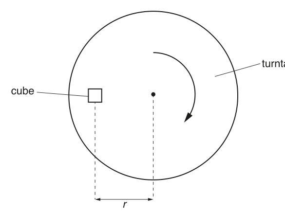
The cube is placed at a distance from the centre of the turntable. It is suggested that the relationship between and the maximum frequency of the turntable for which the cube does not move relative to the turntable is
where is the mass of the cube and is a constant.
Design a laboratory experiment to test the relationship between and . Explain how your results could be used to determine a value for . You should draw a diagram, on page 3, showing the arrangement of your equipment. In your account you should pay particular attention to
• the procedure to be followed,
• the measurements to be taken,
• the control of variables,
• the analysis of the data,
• any safety precautions to be taken.
Answer
Variables
- Independent variable: distance of cube from centre of turntable.
- Dependent variable: maximum frequency for which cube does not move relative to turntable.
- Controlled variables: same cube (mass ), same turntable surface/condition (clean and dry), same face of cube in contact, turntable kept horizontal, same criterion for “just starts to move”.
Apparatus
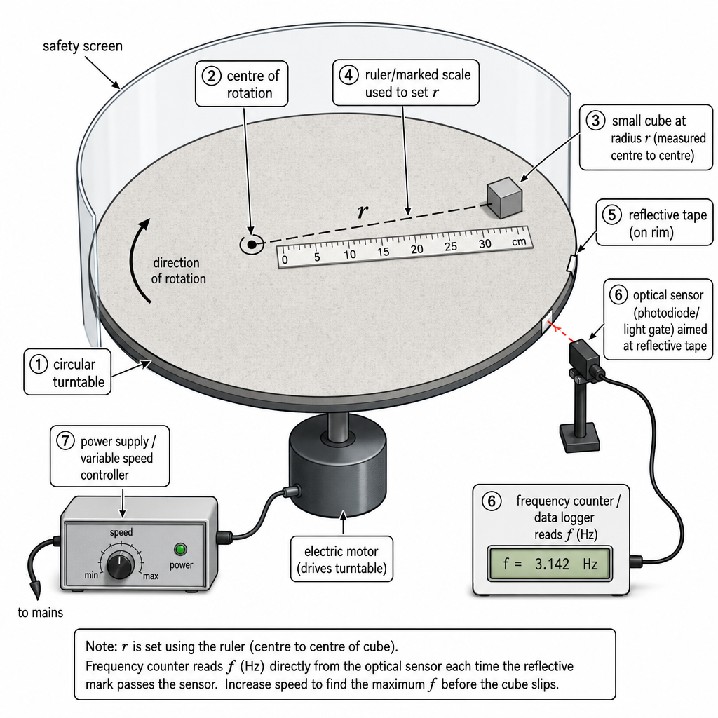
Turntable + variable speed motor and power supply, cube, ruler/vernier callipers to measure , optical sensor/light gate (or photodiode) + data logger/counter with reflective tape marker on turntable to measure , eye protection / safety screen.
Procedure and measurements
- Measure mass of cube using a balance.
- Mark several radii on the turntable. Place the cube so that the centre of the cube is at measured distance from the centre (measure with ruler; record to nearest mm).
- Start turntable at low speed and increase speed slowly.
- Define the slip condition, e.g. “cube shifts by relative to a fixed mark within ”.
- Record the frequency using the optical sensor at the highest speed at which the cube still does not slip (take as the value just before slip).
- Repeat steps 2–5 for at least 6 values of over a wide range. Repeat each measurement at least twice and take a mean.
Analysis (to test the relationship and find )
Given
Rearrange to linear form:
Plot a graph of (y-axis) against (x-axis).
- A straight line through the origin supports the suggested relationship.
- Gradient , hence
(use in , in , in ).
Safety
- Use a safety screen / keep face away: cube could fly off at high speed.
- Switch off motor before repositioning the cube.
- Keep loose clothing/hair away from rotating turntable.
- Increase speed slowly and do not exceed safe rotation speed.
See working
Background Concept
For uniform circular motion, an object moving in a circle of radius at angular speed needs a centripetal force
with . In this experiment, the cube is carried around by the turntable. The cube will only remain at rest relative to the turntable if the available frictional force is large enough to provide the required centripetal force. As the frequency increases, the required centripetal force increases, and at some point the cube starts to slip.
The question supplies a suggested relationship
where is constant for the cube–surface system being used. Even if you would normally expect in a centripetal-force argument, in Paper 5 you must test the relationship as given: choose measurements and a graph that would confirm proportionalities and allow to be determined from a gradient.
Understanding the Question
You must design an experiment where you:
- place the cube at a known distance from the centre,
- find the maximum frequency at which it does not move relative to the turntable,
- repeat for several values of ,
- analyse the data to test whether and fit the supplied equation, and
- use the graph to obtain a value for .
This is a “threshold” measurement: you are not measuring at random; you are finding the limiting value just before slipping occurs.
Approach
- Choose variables: vary (easy to set precisely) and measure the corresponding .
- Measure reliably: use an optical sensor/counter with a single reflective marker on the turntable so you get frequency directly in .
- Define a slip criterion: otherwise different runs give different “maximum” values. A fixed, observable rule (e.g. a certain displacement in a fixed time) makes the threshold reproducible.
- Linearise the equation: rearrange into so that a straight-line graph tests the relationship and the gradient gives .
- Control variables + safety: same cube and surface, consistent placement/orientation, switch off before adjustments, safety screen for flying cube.
Step-by-Step Reasoning
1) Selecting and controlling variables
- Independent variable: .
- Dependent variable: .
- Controls:
- Use the same cube throughout, so is constant.
- Use the same turntable surface condition: wipe it clean/dry so frictional properties are steady.
- Keep the turntable horizontal (spirit level if available). If tilted, a component of weight changes the normal reaction and affects friction.
- Place the same face of the cube down each time.
2) Measuring
Measure from the centre of rotation to the centre of the cube (not the nearest edge). Mark radial lines and distances on the turntable; read to the nearest .
3) Measuring and finding the maximum value before slip
- Put reflective tape on the rim (one piece gives one pulse per revolution).
- Place the photodiode/light gate so it detects each pass; connect to a counter/data logger to read .
- Start at low speed and increase the motor speed slowly.
- Decide a clear slip condition, e.g. “cube moves by at least relative to a mark in ”. This avoids subjective judgement.
- Record as the value just before the slip condition is met.
- Repeat for each (at least two repeats) and take the mean, because threshold behaviour can vary slightly due to vibration and tiny differences in placement.
4) Linearising and obtaining
Start with the given relationship:
Rearrange to make the dependent variable the subject:
This matches the straight-line form with:
- gradient
So:
- plot against ;
- a straight line (ideally through the origin) supports the suggested relationship;
- calculate
using the measured and the gradient from the best-fit line.
5) Safety precautions
- Use a safety screen around the turntable or stand well back: the cube can fly off at high speed.
- Switch off the motor before placing/moving the cube.
- Tie back hair and keep loose clothing away from the rotating turntable.
- Increase speed gradually; do not exceed the safe operating speed of the apparatus.
Key Takeaways
- A good plan defines independent/dependent variables, a repeatable measurement criterion, and controls.
- For a suggested relationship, rearrange to linear form and choose a graph where the gradient gives the constant.
- Threshold experiments need careful method: slow changes, clear definition of “just slips”, repeats, and safe working.
Common Mistakes
- Plotting against directly (this will not be linear for ).
- Not defining what “does not move” means (makes subjective and inconsistent).
- Measuring to the edge of the cube rather than to its centre.
- Moving the cube while the turntable is spinning (unsafe and also changes the threshold condition unpredictably).
- Forgetting to measure , so cannot be found from the gradient.
Things to Be Careful About
- Use SI units consistently when calculating : in , in , in .
- Take a wide range of values (not clustered) so the graph gives a reliable gradient.
- When taking the gradient, use a large triangle on the best-fit line and compute .
- Vibrations and airflow can trigger early slipping; keep the apparatus stable and increase speed smoothly.
- Ensure only one reflective marker is used; multiple markers would give an incorrect frequency reading.
The rest of this paper
1 more questions- Q2Analysis, Conclusions and Evaluation15M