Physics 5054/12 — October/November 2024
Cambridge O-Level · Multiple Choice · answer key with instant marking and worked solutions
Topics Kinetic Particle Model of Matter · Energy, Work and Power · Mass, Weight and Density · Reflection and Refraction of Light · Simple Magnetism and Magnetic Fields · Electric Circuits · +17 more
Tap an option under each question to check it — your score builds as you go.
The diagram shows a clothes peg.
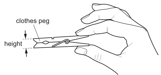
Which device is suitable for obtaining an accurate value for the height of the clothes peg?
Options
A a tape
B a metre rule
C a micrometer
D a measuring cylinder
Working
The diagram indicates the "height" of the clothes peg as the small vertical gap between the two jaws at the front. This is a small linear measurement.
- A tape is flexible and not accurate enough for precise small measurements.
- A metre rule has 1 mm graduations, which is less accurate than a micrometer for small gaps.
- A micrometer (micrometer screw gauge) is designed to measure small lengths accurately to 0.01 mm.
- A measuring cylinder is used for measuring the volume of liquids, not length.
Therefore, a micrometer is the most suitable device for obtaining an accurate value for this small height.
Answer
C
C
Walkthrough
The question asks for the most suitable device to obtain an accurate value for the height of the clothes peg, where the height is indicated as the small vertical gap between the front jaws of the peg.
We evaluate each option:
- A tape: Tape measures are flexible and generally have 1 mm graduations. They are suitable for longer, less precise measurements (like the length of a room) but not for accurate small gaps.
- A metre rule: A standard metre rule has 1 mm graduations. While it can measure small lengths, it is not as accurate as a micrometer for very small distances.
- A micrometer: Also known as a micrometer screw gauge, this instrument is specifically designed to measure small lengths (such as the thickness of a wire or a small gap) accurately to 0.01 mm. It is the most precise tool listed for a small linear measurement.
- A measuring cylinder: This is an instrument used to measure the volume of liquids, not a linear dimension like length or height.
Since the question asks for an accurate value for a small height, the micrometer is the correct choice.
Key Takeaways
- Different measuring instruments have different ranges and precisions. Choose the instrument that matches both the size of the quantity and the required accuracy.
- Micrometers (screw gauges) are used for small, precise linear measurements (e.g., thickness of wire, small gaps).
- Metre rules and tapes are used for larger, less precise measurements.
- Measuring cylinders are for volume, not length.
Common Mistakes
- Choosing a metre rule simply because it can measure length, without considering that the question asks for an accurate value for a small gap, which requires a more precise instrument like a micrometer.
- Choosing a tape because it is commonly used for measuring clothes or pegs, but ignoring its lack of accuracy.
- Choosing a measuring cylinder by misreading "height" as a volume or confusing it with a measuring device.
Things to Be Careful About
- Always read the diagram carefully to see exactly which dimension is being asked for. Here, the "height" is the small vertical gap between the jaws, not the overall length of the peg (which would be around 10 cm and could be measured with a metre rule).
- Pay attention to the word accurate. If a question asks for an accurate measurement of a small length, a micrometer or vernier caliper is required, not a metre rule.
Which set of quantities are all vectors?
Options
A acceleration, displacement, velocity
B chemical energy, mass, power
C extension, force, gravitational potential energy
D weight, kinetic energy, work
Working
A vector is a quantity that has both magnitude and direction.
- A: acceleration, displacement, velocity — all three have direction, so all are vectors.
- B: chemical energy, mass, power — none has direction, so all are scalars.
- C: extension (scalar), force (vector), gravitational potential energy (scalar) — mixed.
- D: weight (vector), kinetic energy (scalar), work (scalar) — mixed.
Only A contains quantities that are all vectors.
Answer
A
A
Walkthrough
A vector is a quantity that has both magnitude (size) and direction. A scalar is a quantity that has magnitude only.
Test each option:
- A — acceleration, displacement and velocity are all directed quantities. Displacement is a distance in a stated direction, velocity is a speed in a stated direction, and acceleration is a change in velocity, so it too has a direction. All three are vectors.
- B — chemical energy, mass and power have no direction. Energy and power are scalars; mass is a scalar. All three are scalars.
- C — force is a vector, but extension (a change in length) and gravitational potential energy (an energy) are scalars. Mixed, so not the answer.
- D — weight is a vector (a force acting downwards), but kinetic energy and work are scalars. Mixed, so not the answer.
Only option A contains quantities that are all vectors.
Key Takeaways
- A vector has both magnitude and direction; a scalar has magnitude only.
- Common vectors: displacement, velocity, acceleration, force, weight, momentum.
- Common scalars: distance, speed, mass, time, temperature, energy, work, power.
- This question tests the ability to sort everyday quantities into the two classes quickly and correctly.
Common Mistakes
- Confusing weight (a force, so a vector) with mass (a scalar).
- Confusing displacement (vector) with distance (scalar), and velocity (vector) with speed (scalar).
- Thinking that because work = force × distance, work must be a vector — it is not; work and all forms of energy are scalars.
- Thinking that power is a vector because it involves force — power is a scalar.
Things to Be Careful About
- Force is a vector, but the quantities derived from it are not automatically vectors: work and pressure are scalars.
- Extension is a change in length, so it is a scalar even though it is caused by a force.
- Acceleration is a vector even in straight-line motion; its direction is the direction of the change in velocity.
The graph shows the motion of a cyclist during a ride that lasts for .
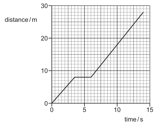
What is the average speed of the cyclist for the ride?
Options
A
B
C
D
Working
The average speed is defined as the total distance travelled divided by the total time taken.
From the distance-time graph (Fig. 1):
- The ride lasts for a total time of .
- At , the total distance travelled is read from the vertical axis. The graph ends at a distance of .
Answer
A
A
Walkthrough
- Identify the goal: The question asks for the average speed of the cyclist for the entire ride. Average speed is a global property of the trip, not the speed at any particular moment.
- Recall the formula: The formula for average speed is:
- Read the total time: The question states the ride lasts for . We can also verify this on the graph; the horizontal axis (time) goes from 0 to 15, and the graph line ends at (one major grid unit before 15, where each major unit is 1 s).
- Read the total distance: Look at the vertical axis (distance) at the end of the graph line (). The vertical axis has major markings at 0, 10, 20, 30. There are 5 large squares between 0 and 10, so each large square represents . The graph ends 4 large squares below 30, which is ? No, let's look closer. 20 is a line. 4 squares above 20 is . The graph ends at .
- Calculate: Substitute the values into the formula:
- Match with options: The calculated value is , which corresponds to option A.
Key Takeaways
- Average speed depends only on the total distance and total time for the whole journey. The details of the motion (stopping, speeding up, slowing down) do not matter for the average speed calculation.
- Distance-time graphs: The vertical axis gives the total distance from the start at any given time. The gradient (slope) at any point gives the instantaneous speed at that time.
Common Mistakes
- Calculating the speed of a specific section: Candidates might calculate the speed during the final moving phase (from to ). Distance = , Time = , Speed = . This matches option D, but it is the speed during the last part, not the average speed for the whole ride.
- Reading the graph incorrectly: Misreading the final distance value (e.g., reading 32 m or 30 m) would lead to incorrect answers like B or C.
- Confusing distance and displacement: In 1D motion without turning back, distance equals the magnitude of displacement. Here, the cyclist moves forward, stops, then moves forward again. Total distance is simply the final y-value.
Things to Be Careful About
- Graph reading precision: Ensure you read the grid correctly. The x-axis has 5 large squares per 5 seconds (1 s per large square). The y-axis has 5 large squares per 10 meters (2 m per large square). The final point is at .
- Definition of average speed: Do not average the speeds of different sections (e.g., speed in first part + speed in second part divided by 2). That is a common mathematical error. Always use .
- Units: Ensure the final answer is in . The graph axes are in meters and seconds, so the result is naturally in .
The diagram shows how the velocity of a train varies with time.
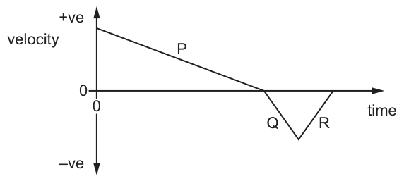
Which sections of the graph show where the magnitude of the velocity of the train is decreasing?
Options
A P and Q
B P and R
C P only
D R only
Answer
The magnitude of velocity is the speed. On the velocity–time graph, speed is decreasing whenever the graph moves towards the time axis (where velocity = 0).
- Section P: velocity falls from a positive value to 0. Speed decreases.
- Section Q: velocity falls from 0 to a negative peak. Speed increases.
- Section R: velocity rises from a negative peak to 0. Speed decreases.
The sections where the magnitude of velocity is decreasing are P and R.
Answer
B
B
Walkthrough
The question asks for sections where the magnitude of the velocity is decreasing. The magnitude of velocity is speed. On a velocity-time graph, speed is the absolute value of the velocity, meaning we look for sections where the graph is moving towards the time axis (velocity = 0).
- In section P, the velocity goes from a positive value down to 0. The speed is decreasing.
- In section Q, the velocity goes from 0 down to a negative peak. The speed (magnitude) is increasing.
- In section R, the velocity goes from the negative peak back up to 0. The speed (magnitude) is decreasing.
Thus, P and R are the correct sections.
Key Takeaways
- Velocity is a vector; its magnitude is speed.
- On a velocity-time graph, decreasing speed corresponds to the graph moving towards the time axis (v = 0), regardless of whether the velocity is positive or negative.
Common Mistakes
- Confusing 'velocity decreasing' with 'speed decreasing'. Velocity is decreasing throughout P, Q, and R (the gradient is negative everywhere), but speed only decreases in P and R.
- Forgetting that a negative velocity with an increasing magnitude (becoming more negative) means speed is increasing.
Things to Be Careful About
- Always read 'magnitude of velocity' as 'speed'.
- Check the sign of the velocity: if it is negative and moving away from zero, the magnitude is increasing.
A metal disc is squeezed in the jaws of a vice.
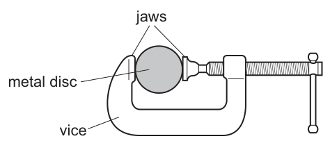
Which property of the metal disc is unchanged when it is squeezed?
Options
A mass
B radius
C distance between its atoms
D forces between its atoms
Working
Mass is the amount of matter in an object. Squeezing the disc changes its shape but does not add or remove matter, so the mass is unchanged.
- B (radius): The disc flattens, so its radius in the direction of the squeeze decreases and increases in the perpendicular direction.
- C (distance between atoms): The atoms are displaced; they move closer together in the direction of compression and further apart sideways.
- D (forces between atoms): As atoms are pushed closer than their equilibrium separation, the repulsive intermolecular forces increase to resist the deformation.
Answer
A
A
Walkthrough
The question asks which property of a metal disc remains unchanged when it is squeezed in a vice. We evaluate each option using the definition of mass and the kinetic particle model of solids.
- Option A (mass): Mass is a measure of the amount of matter in an object. Squeezing the disc deforms it but does not add or remove any metal atoms. Therefore, the mass is conserved and unchanged.
- Option B (radius): As the circular disc is squeezed, it flattens into an oval or elliptical shape. The radius in the direction of the squeezing force decreases, while the radius in the perpendicular direction increases. Thus, the radius changes.
- Option C (distance between its atoms): In a solid, atoms are arranged in a regular lattice. When squeezed, the lattice is distorted. The atoms move closer together in the direction of the applied force and spread further apart in the perpendicular direction. The distances between atoms therefore change.
- Option D (forces between its atoms): Atoms in a solid are held at an equilibrium separation by attractive and repulsive forces. When the disc is squeezed, atoms are pushed closer together than their equilibrium separation. This increases the repulsive forces between them, which is why the metal resists being squeezed. Thus, the forces between atoms change.
Key Takeaways
- Mass is an intrinsic property representing the amount of matter; it does not change with shape, volume, or position.
- Deforming a solid changes its macroscopic dimensions (like radius) and its microscopic atomic arrangement (distances and forces between atoms), but not the total amount of matter.
Common Mistakes
- Thinking that mass changes when the shape of an object changes. Mass is conserved during deformation.
- Assuming that the distance between atoms in a solid is fixed. While solids are rigid, their atomic lattice can be distorted under force, changing interatomic distances.
- Confusing mass with weight. While weight is also unchanged here (assuming is constant), it is not an option, and mass is the fundamental property being tested.
Things to Be Careful About
- Ensure you distinguish between macroscopic properties (radius, shape) and microscopic properties (atomic distances, intermolecular forces). Both can change during deformation.
- Remember that 'mass' refers to the quantity of matter, not the volume or density. Volume and density will change as the shape changes (if the volume is conserved, density is constant; if volume changes due to compression, density changes, but mass remains constant).
The gravitational field strength in space is smaller than on the Earth’s surface.
How are the mass and the weight of a satellite affected as the satellite moves away from the surface of the Earth and into space?
Options
A Both the mass and the weight are unaffected.
B The mass decreases and the weight decreases.
C The mass increases and the weight is unaffected.
D The mass is unaffected and the weight decreases.
Working
Mass is the amount of matter in the satellite, so it does not change as the satellite moves away from the Earth. Weight is the gravitational force on the satellite, given by . As the satellite moves into space, decreases, so the weight decreases.
Option A is wrong because the weight is affected. Option B is wrong because the mass does not decrease. Option C is wrong because the mass does not increase and the weight is affected.
Answer
D
D
Walkthrough
Mass is a property of the object itself: it is the amount of matter in the satellite, so it stays the same wherever the satellite is. Weight is the gravitational force acting on the object, and it is calculated using , where is the mass and is the gravitational field strength.
On the Earth's surface, is about 10 N/kg. In space, the gravitational field strength is smaller, so the same mass gives a smaller weight. Therefore the correct answer is D: the mass is unaffected and the weight decreases.
Option A is wrong because the gravitational field strength is smaller in space, so the weight cannot be unaffected. Option B is wrong because mass does not depend on gravity. Option C is wrong because mass does not increase and weight is not unaffected.
Key Takeaways
- Mass is the amount of matter in an object and is measured in kilograms.
- Weight is a force, measured in newtons, and equals the mass multiplied by the gravitational field strength.
- Mass stays the same everywhere; weight changes when the gravitational field strength changes.
- A satellite in space still has weight, but it is smaller than on the Earth's surface.
Common Mistakes
- Thinking that mass decreases in space. Mass is not affected by gravitational field strength.
- Confusing mass with weight and choosing an option that treats them as the same thing.
- Forgetting that weight is a force, so it depends on the value of .
Things to Be Careful About
- The question says the gravitational field strength is smaller, not zero, so the weight decreases but is not necessarily zero.
- Mass is measured in kg, while weight is measured in N.
- When using , use the gravitational field strength in N/kg and mass in kg.
A material has a density of .
What is the density in ?
Options
A
B
C
D
Working
Convert the mass and volume units separately.
1 kg = 1000 g, so 1 g = 0.001 kg = kg.
1 m = 100 cm, so . Therefore, .
Substitute these into the density:
Answer
D
D
Walkthrough
This is a unit conversion problem. The density is given as , and we must express it in . The key is to convert the mass unit (g to kg) and the volume unit (cm³ to m³) separately.
- Convert mass: There are 1000 grams in a kilogram, so .
- Convert volume: There are 100 centimetres in a metre. Since the unit is cubic, we must cube this conversion factor: . This means .
- Combine the conversions: Substitute these into the density, treating the units as algebraic quantities. The in the denominator of the density is replaced by . This gives .
- Final answer: , so the density is . This matches option D.
Key Takeaways
- Unit conversion is a core skill: This question tests the ability to convert between units of density, which is a fundamental physical property.
- Cubic units: The most common mistake is forgetting to cube the linear conversion factor for volume. A factor of 100 for length becomes a factor of for volume.
- Powers of ten: Being comfortable with scientific notation and powers of ten is essential for solving these types of problems quickly and accurately.
Common Mistakes
- Forgetting to cube the conversion factor: A very common error is to convert to using a factor of 100 instead of . This would give , which is option B.
- Incorrect direction of conversion: Dividing instead of multiplying by would give , which is not an option but is a common slip.
- Not using standard form: Attempting to write out as 1,000,000 can lead to errors in counting zeros, especially when dividing.
Things to Be Careful About
- Always cube the linear conversion factor when dealing with volume or area units.
- Check the order of magnitude. The density of most solids and liquids is on the order of , so an answer like should immediately look wrong for a solid material.
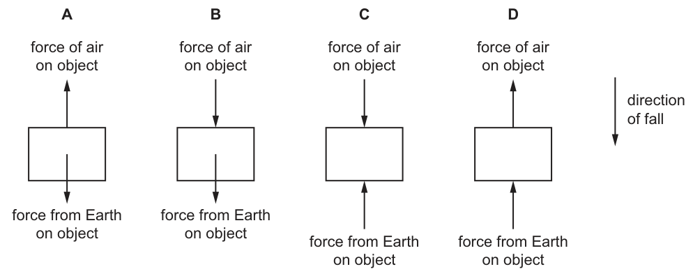
An object falls vertically through the air.
Which diagram represents the forces acting on the object?
Options
Answer
A
A
Walkthrough
The object is falling vertically downwards, as indicated by the 'direction of fall' arrow in the diagrams. There are two forces acting on the object:
- Weight (labelled 'force from Earth on object'): This is the gravitational pull of the Earth. Weight always acts vertically downwards, towards the centre of the Earth. Therefore, the arrow for this force must point down.
- Air resistance (labelled 'force of air on object'): This is a drag force that opposes the motion of the object through the air. Since the object is moving downwards, the air resistance must act upwards. Therefore, the arrow for this force must point up.
Diagram A is the only diagram that correctly shows the force from Earth pointing down and the force of air pointing up.
Key Takeaways
- Weight is the force exerted by a gravitational field (Earth) on a mass, and it always acts downwards.
- Air resistance (or drag) is a frictional force that always acts in the direction opposite to the motion of the object through a fluid (air or liquid).
- In a free-body diagram, only forces are drawn as arrows. The direction of motion (velocity) is not a force and is not drawn as a force arrow.
Common Mistakes
- Choosing a diagram where air resistance points downwards, confusing the direction of motion with the direction of the drag force.
- Thinking that because the object is falling, all forces must point downwards.
- Including the 'direction of fall' as a force arrow in the diagram.
Things to Be Careful About
- Always distinguish between the direction of motion (velocity) and the direction of forces. Forces cause changes in motion, they do not necessarily point in the direction of motion.
- Remember that weight is a force towards the Earth, so it is always downwards regardless of whether the object is moving up, down, or sideways.
A force is applied to a lever at distance from the pivot as shown.
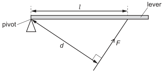
Length is the perpendicular distance between the force and the pivot.
Which expression is the moment of force about the pivot?
Options
A
B
C
D
Working
The moment of a force about a pivot is defined as the product of the force and the perpendicular distance from the pivot to the line of action of the force.
In the diagram, is the perpendicular distance from the pivot to the line of action of . The distance is measured along the lever and is not the perpendicular distance.
Option C matches this expression.
Answer
C
C
Walkthrough
The question asks for the expression for the moment of force about the pivot. The fundamental definition of the moment of a force is the product of the applied force and the perpendicular distance from the pivot to the line of action of that force. Looking at Fig. 1, the force is applied at an angle to the lever. The distance is measured along the lever from the pivot to the point of application, but this is not the perpendicular distance. The perpendicular distance from the pivot to the line of action of is explicitly labelled as . Therefore, the moment is simply . Option D () is a common distractor for candidates who forget that the distance must be measured perpendicularly from the pivot to the line of action.
Key Takeaways
- The moment of a force is , where is the perpendicular distance from the pivot to the line of action of the force.
- The distance along the lever () is not used directly in the moment calculation unless the force is applied perpendicularly to the lever.
Common Mistakes
- Using the distance along the lever () instead of the perpendicular distance (). This leads to choosing option D.
- Dividing the force by the distance instead of multiplying, leading to option A or B.
Things to Be Careful About
- Always check whether the given distance is perpendicular to the line of action of the force. If the force is applied at an angle, you must use the perpendicular distance from the pivot to the line of action, not the distance along the lever.
A rocket is launched vertically upwards by a constant force from its engines.
The data for the launch is shown.
| weight of rocket | |
| average air resistance | |
| force from engine |
How much of the work done on the rocket is used to increase its speed in the first ?
Options
A
B
C
D
Working
The work done to increase the speed is the work done by the resultant force on the rocket.
Resultant force = upward force − weight − air resistance
Answer
A
A
Walkthrough
This question asks for the work done to increase the rocket's speed. Work done is the product of the resultant force and the distance moved in the direction of that force. The rocket is moving upwards, so we first find the net upward force.
The forces are:
- Upward engine force:
- Downward weight:
- Downward air resistance:
The resultant force is:
Then, work done is:
So the correct answer is A.
- B (170 MJ) is the work done if you forgot to include air resistance (i.e., using 1.7 MN as the resultant force).
- C (350 MJ) is the work done by the engine force alone, ignoring weight and air resistance.
- D (550 MJ) is the work done if you added the forces instead of subtracting (3.5 + 1.9 + 0.1 = 5.5 MN).
Key Takeaways
- Work done to increase speed is calculated using the resultant force, not just any individual force.
- Always identify the direction of each force and combine them as vectors (here, all forces are along a line).
- Convert units (MN to N) before calculating.
Common Mistakes
- Forgetting to subtract air resistance – leads to option B.
- Using the engine force alone – leads to option C. The weight and air resistance oppose the motion.
- Adding all forces – leads to option D. This is incorrect because weight and air resistance act opposite to the engine force.
Things to Be Careful About
- The unit MN (meganewton) must be converted to newtons: .
- Work is a scalar, but you must use the resultant force in the direction of motion.
- The distance is already in metres, so no conversion is needed there.
Which equation is used to calculate the efficiency of an energy transfer?
Options
A
B
C
D
Working
Efficiency is defined as the ratio of the useful energy output to the total energy input.
Answer
A
A
Walkthrough
Efficiency tells us how good a device or system is at transferring energy usefully. It is always a ratio of what you get out that is useful, divided by what you put in. So, efficiency = (useful energy output) / (total energy input). Option A matches this definition exactly.
Option B is the inverse, which would give a value greater than 1 (more than 100%), which is impossible for efficiency. Option C incorrectly uses power instead of energy, and Option D multiplies the two quantities, which would give incorrect units and not a ratio.
Key Takeaways
- Efficiency is a measure of how well energy is converted into a useful form.
- It is always calculated as (useful output) divided by (total input).
- Since it is a ratio, it has no units and is often expressed as a percentage.
Common Mistakes
- Choosing option B, which inverts the ratio. Remember, efficiency cannot be greater than 1 (or 100%).
- Confusing energy with power. Efficiency compares energy (or power) output to energy (or power) input, but the question specifically asks for energy transfer.
Things to Be Careful About
- Remember that efficiency is a ratio, so it has no units.
- Ensure you are comparing the same quantity (energy in this case) in the numerator and denominator.
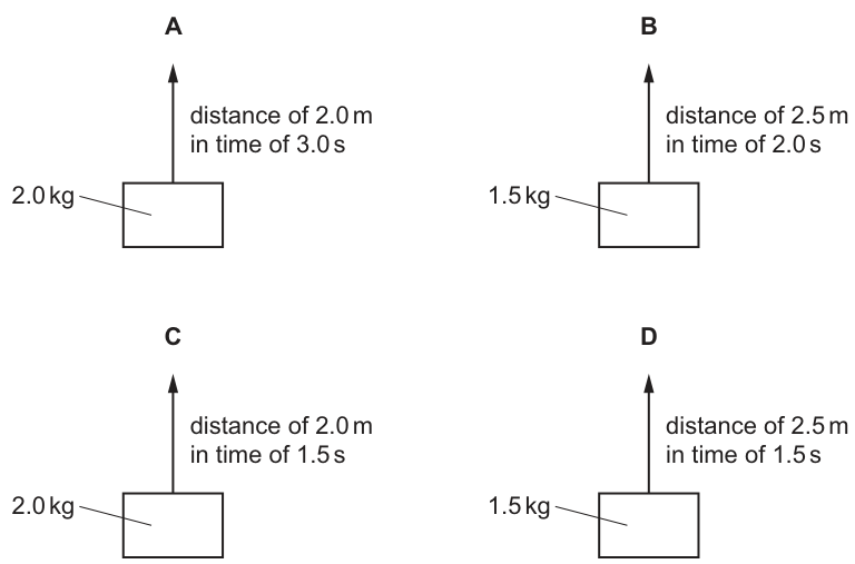
Four objects of different masses are lifted through different distances in different amounts of time.
In which combination of mass, distance and time is the greatest power transferred?
Options
Working
Power is the rate of doing work:
When lifting an object, the work done is equal to the gain in gravitational potential energy:
Therefore,
Since is the same for all options (approximately ), we can compare the value of to find the greatest power.
-
Option A: , ,
-
Option B: , ,
-
Option C: , ,
-
Option D: , ,
Comparing the values (), option C has the greatest power.
Answer
C
C
Walkthrough
The question asks for the greatest power transferred when lifting objects. Power is defined as the rate at which work is done, given by the equation . When lifting an object vertically against gravity, the work done is equal to the force applied (weight, ) multiplied by the distance lifted ( or ). So, .
Substituting this into the power equation gives . Since the gravitational field strength is constant for all four options (we can use for calculation), the power is directly proportional to . We can calculate the power for each option to find the maximum.
- For A: Mass , distance , time . Work done . Power .
- For B: Mass , distance , time . Work done . Power .
- For C: Mass , distance , time . Work done . Power .
- For D: Mass , distance , time . Work done . Power .
The highest value is , which corresponds to option C.
Key Takeaways
- Power is the rate of doing work: .
- Work done against gravity is calculated as (mass g height/distance).
- To compare power in different scenarios where is constant, you can compare the ratio .
Common Mistakes
- Confusing power with work or energy: A student might calculate the work done () and stop there. Option A and C have the same work done (), but C is faster, so it has more power. Option B and D have less work done ().
- Forgetting to divide by time: Power depends on how quickly the work is done. Option D has a shorter time than B, so it has higher power despite the same work. Option C has the shortest time combined with the highest work (tied with A), making it the winner.
- Using the wrong formula: Using might be valid if velocity was constant and calculated, but is more direct here.
Things to Be Careful About
- Units: Ensure mass is in kg, distance in m, and time in s to get power in Watts (J/s). The values given are already in standard units.
- Value of : The mark scheme accepts calculations using or . Since we are comparing ratios, the specific value of does not change the final answer, but it must be consistent if calculating exact values.
- Significant figures: The calculations result in repeating decimals (e.g., ). Rounding to 2 or 3 significant figures is sufficient for comparison (, , , ).
Air at a pressure of is trapped in a container by a piston.
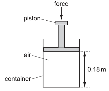
A force is applied to move the piston down into the container. The temperature of the air remains constant. The distance between the base of the container and the piston decreases from to .
What is the new air pressure inside the container?
Options
A
B
C
D
Working
Since the cross-sectional area of the container is constant, volume , so the equation becomes:
Answer
C
C
Walkthrough
The question states that the temperature of the trapped air remains constant while the piston is pushed down. This is a classic application of Boyle's law, which is expressed in the 5054 syllabus as for a fixed mass of gas at constant temperature.
The container has a uniform cross-section, so its volume is proportional to the height of the air column: . The area cancels out when we substitute into the gas law, leaving .
Rearranging for the new pressure gives .
Substituting the given values: , , and .
.
This matches option C.
Key Takeaways
- Boyle's law () applies when temperature and mass are constant.
- For a container with uniform cross-section, volume is proportional to height, so .
Common Mistakes
- Inverting the ratio and calculating , which gives (option B). Pressure must increase when volume decreases.
- Forgetting to include the factor and getting instead of .
Things to Be Careful About
- Ensure the units of height are consistent (both in metres here, so no conversion needed).
- Remember that decreasing volume at constant temperature must result in an increase in pressure; if your answer is less than the initial pressure, you have inverted the ratio.
A sealed gas syringe contains a gas that is kept at constant volume.
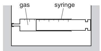
Which row describes how a change in the temperature of the gas affects its pressure?
Options
| temperature | pressure of gas | |
|---|---|---|
| A | decreases | increases |
| B | decreases | unchanged |
| C | increases | increases |
| D | increases | unchanged |
Working
Gas pressure at constant volume is caused by particle collisions with the container walls. An increase in temperature increases the average kinetic energy of the gas particles, making them move faster. Faster particles collide with the walls more frequently and with greater force, so the pressure increases. Therefore, if the temperature increases, the pressure increases.
Answer
C
C
Walkthrough
The question asks about the relationship between temperature and pressure for a gas held at constant volume. According to the kinetic particle model, gas pressure arises from the continuous collisions of gas particles with the walls of the container. When the temperature of the gas increases, the thermal energy of the particles increases, which means their average kinetic energy increases. As a result, the particles move at higher speeds. Faster-moving particles collide with the container walls more often and with greater momentum change per collision. Both of these effects (more frequent collisions and harder collisions) cause the pressure to increase. Conversely, if the temperature decreases, the particles slow down and the pressure falls. Therefore, the only row that correctly describes a valid cause-and-effect relationship is C: temperature increases, pressure increases.
Key Takeaways
- Gas pressure is caused by particle collisions with the container walls.
- Temperature is a measure of the average kinetic energy of the particles.
- At constant volume, increasing temperature increases particle speed, leading to more frequent and more forceful collisions, which increases pressure.
Common Mistakes
- Confusing the effect of volume on pressure with the effect of temperature. At constant volume, only temperature changes affect pressure in this scenario.
- Thinking that pressure remains unchanged if the container is rigid, without considering that temperature changes still alter particle speeds and collision forces.
Things to Be Careful About
- Ensure you read the question carefully to note that the volume is constant. If the volume were allowed to change (e.g., a free-moving piston), the outcome would be different.
- Remember that temperature must be in kelvin for quantitative calculations using gas laws, but the qualitative relationship (higher temperature = higher pressure at constant volume) holds regardless.
The melting temperature of gold is .
What is the melting temperature of gold on the Kelvin scale?
Options
A
B
C
D
Working
To convert a temperature from degrees Celsius to kelvin, add 273:
Answer
D
D
Walkthrough
The Kelvin scale is the thermodynamic temperature scale, and it is related to the Celsius scale by a simple fixed shift. A temperature difference of 1 kelvin is exactly the same size as a temperature difference of 1 degree Celsius, so the two scales only differ in where their zero sits.
Absolute zero on the Kelvin scale is , which corresponds to on the Celsius scale. This means that to convert any Celsius temperature into kelvin you add 273:
For gold, the melting temperature is , so:
That matches option D.
Each of the other options comes from a misunderstanding of the conversion. Option A () is , subtracting instead of adding. Option B () is , a made-up shift of 100. Option C () is , again using 100 instead of 273. Only option D uses the correct shift of 273.
Key Takeaways
- The Kelvin and Celsius scales have the same size of degree; they differ only in their zero points.
- Absolute zero is , so .
- A temperature given in kelvin is always numerically larger than the same temperature in degrees Celsius by 273.
Common Mistakes
- Subtracting 273 instead of adding it, which gives option A ().
- Using 100 as the conversion shift instead of 273, which gives options B and C.
- Forgetting that the conversion is an addition of 273, not a multiplication or a shift of 100.
Things to Be Careful About
- Always add 273 when going from Celsius to kelvin, and subtract 273 when going from kelvin to Celsius.
- The unit for the kelvin scale is written as K with no degree symbol, so the answer is , not .
- If a question gives a temperature in kelvin and asks for Celsius, the answer will be numerically smaller by 273.
The table shows the melting and boiling temperatures of three elements.
| element | melting temperature / | boiling temperature / |
|---|---|---|
| argon | –189 | –185 |
| nitrogen | –210 | –196 |
| oxygen | –218 | –183 |
At which temperature are the three elements in different states?
Options
A
B
C
D
Working
For each element:
- below the melting temperature → solid
- between the melting and boiling temperatures → liquid
- above the boiling temperature → gas
Check each option:
A : argon solid, nitrogen solid, oxygen solid — all solid.
B : argon solid, nitrogen liquid, oxygen liquid — not all different.
C : argon solid (below ), nitrogen gas (above ), oxygen liquid (between and ) — three different states.
D : argon gas, nitrogen gas, oxygen gas — all gas.
Answer
C
C
Walkthrough
A substance is in one of three states depending on its temperature relative to its melting and boiling points:
- solid below the melting temperature,
- liquid between the melting and boiling temperatures,
- gas above the boiling temperature.
We must find the single temperature at which argon, nitrogen and oxygen are in three different states.
- At , all three elements are below their melting points, so all are solid.
- At , argon is solid (below ), while nitrogen and oxygen are both liquid (each between its melting and boiling points). Two liquids, one solid — not three different states.
- At , argon is solid (below its melting point of ), nitrogen is gas (above its boiling point of ), and oxygen is liquid (between and ). This gives three different states, so C is correct.
- At , all three elements are above their boiling points, so all are gas.
Key Takeaways
The state of a substance depends only on where its temperature sits relative to its melting and boiling points. Comparing several temperatures against the given data, one at a time, is the reliable method.
Common Mistakes
- Confusing the direction of the inequalities: a temperature more negative than the melting point means solid, not liquid.
- Reading as above argon's melting point of ; is actually below , so argon is solid there.
- Forgetting that a substance above its boiling point is a gas, not a liquid.
Things to Be Careful About
- All temperatures here are negative, so "higher" means less negative (e.g. is higher than ).
- Check each element separately at each option temperature before deciding.
- The correct option is the only one where the three states are all different.
The diagram shows a liquid at room temperature in a beaker.
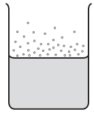
What reduces the rate of loss of liquid by evaporation?
Options
A blowing air across the top of the beaker
B heating the liquid
C putting a lid on the beaker
D transferring the liquid to a beaker with a larger diameter
Answer
C
C
Walkthrough
Evaporation is the escape of molecules from the surface of a liquid at temperatures below the boiling point. The rate of evaporation depends on four main factors:
- Temperature: Higher temperature means molecules have more kinetic energy, so more can escape. Heating the liquid (Option B) increases the rate.
- Surface area: A larger surface area exposes more molecules to the air. Transferring to a beaker with a larger diameter (Option D) increases the rate.
- Air movement: Blowing air across the surface (Option A) removes the vapour molecules that have just escaped, preventing them from condensing back into the liquid, which increases the rate.
- Vapour concentration: If the air above the liquid is saturated with vapour, evaporation slows down. Putting a lid on the beaker (Option C) traps the vapour above the liquid, increasing the vapour concentration and reducing the net rate of evaporation.
Therefore, putting a lid on the beaker is the only action that reduces the rate of loss of liquid by evaporation.
Key Takeaways
The rate of evaporation is increased by: higher temperature, larger surface area, air movement across the surface, and lower vapour concentration above the liquid. Conversely, a lid or cover reduces the rate by trapping vapour.
Common Mistakes
- Choosing Option A, thinking that blowing air cools the liquid and therefore reduces evaporation. While blowing air does increase cooling by evaporation, it actually increases the rate of evaporation itself.
- Choosing Option D, confusing surface area effects. A larger diameter means a larger surface area, which increases evaporation, not reduces it.
Things to Be Careful About
Read the question carefully: it asks what reduces the rate of loss, not what increases it. Options A, B, and D all increase the rate of evaporation. Only Option C reduces it.
What is the colour and what is the texture of the best absorber of infrared radiation?
Options
A black and shiny
B black and dull
C white and shiny
D white and dull
Working
The best absorber of infrared radiation is a surface that is black and dull. Black surfaces absorb more thermal radiation than white surfaces, and dull surfaces absorb more than shiny surfaces because shiny surfaces reflect some radiation.
Answer
B
B
Walkthrough
The question asks which surface absorbs infrared radiation best. Infrared radiation is thermal radiation, and its absorption depends on both the colour and the texture of the surface.
- Colour: Black surfaces absorb more infrared radiation than white surfaces. White surfaces reflect most of the radiation, so they stay cooler when exposed to infrared.
- Texture: Dull surfaces absorb more infrared radiation than shiny surfaces. A shiny surface reflects a large amount of the radiation away, so it is not a good absorber.
Therefore, the best absorber is black and dull, which is option B.
Key Takeaways
- The best absorber and emitter of infrared radiation is a black, dull surface.
- The best reflector of infrared radiation is a white, shiny surface.
- The same surface properties that make a good absorber also make a good emitter of infrared radiation.
Common Mistakes
- Choosing black and shiny: a shiny surface reflects some infrared radiation, so it is not the best absorber.
- Choosing white and dull: a white surface reflects most infrared radiation, regardless of texture.
- Confusing the best absorber with the best reflector: the question asks about absorption, not reflection.
Things to Be Careful About
- “Texture” here means dull/matte versus shiny, not whether the surface is rough or smooth in a general sense.
- A dull black surface is also the best emitter of infrared radiation, which is often tested alongside absorption.
- Read the options carefully: both colour and texture must be correct to score the mark.
Which row gives the velocity and wavelength of a wave that is an ultrasound wave?
Options
| velocity / | wavelength / | |
|---|---|---|
| A | 330 | 6.6 |
| B | 890 | 89 |
| C | 1500 | 6.0 |
| D | 4000 | 25 |
Working
Ultrasound is sound with a frequency above . For each row, find the frequency using
with converted to metres.
A: — audible
B: — audible
C: — ultrasound ✓
D: — audible
Answer
C
C
Walkthrough
Ultrasound is defined as sound with a frequency higher than 20 kHz (20 000 Hz), which is above the human audible range. The question gives velocity and wavelength for four waves, and we need to identify the one that is ultrasound.
The wave equation links these quantities: , so the frequency is . Before dividing, we must convert the wavelength from cm to m (6.6 cm = 0.066 m, 89 cm = 0.89 m, 6.0 cm = 0.060 m, 25 cm = 0.25 m).
Row A: 330 m/s is the speed of sound in air; , which is audible, not ultrasound.
Row B: , audible.
Row C: 1500 m/s is the speed of sound in water (and body tissue); , which is above 20 kHz, so this is ultrasound. ✓
Row D: , still audible (just below the 20 kHz threshold).
So C is the correct answer.
Key Takeaways
- Ultrasound is sound with a frequency above 20 kHz.
- The wave equation lets you find the frequency from the velocity and wavelength.
- The speed of sound differs in different media: about 330 m/s in air and about 1500 m/s in water (and body tissue), which is why medical ultrasound uses the 1500 m/s value.
Common Mistakes
- Forgetting to convert the wavelength from cm to m before dividing — this gives a frequency 100 times too large.
- Thinking ultrasound must travel in air at 330 m/s; in fact medical ultrasound travels in water/gel.
- Confusing wavelength with frequency, or picking a row just because the velocity looks familiar.
Things to Be Careful About
- Convert 6.0 cm to 0.060 m before using .
- Remember the threshold: 20 kHz = 20 000 Hz.
- A wave with frequency below 20 kHz is audible, not ultrasound, even if it has a high velocity.
The diagram shows a ray of light incident on a plane mirror.
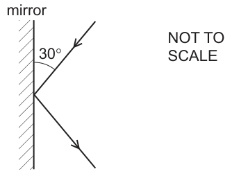
What is the angle of reflection?
Options
A
B
C
D
Working
The angle given in the diagram () is between the incident ray and the mirror surface. By definition, the angle of incidence is measured between the incident ray and the normal (a line perpendicular to the mirror surface).
The law of reflection states that the angle of reflection equals the angle of incidence ().
Answer
B
B
Walkthrough
The problem asks for the angle of reflection for a ray hitting a plane mirror. The diagram provides the angle between the incident ray and the mirror surface (). In physics, angles in reflection are always measured from the normal, which is an imaginary line drawn perpendicular () to the mirror surface at the point of incidence.
- Find the angle of incidence (): Since the normal is at to the mirror, the angle of incidence is the complement of the angle given. .
- Apply the law of reflection: The law states that the angle of reflection () is equal to the angle of incidence (). Therefore, .
- Select the option: Option B matches this value.
Key Takeaways
- The angle of incidence and angle of reflection are always measured from the normal, not from the mirror surface.
- The law of reflection is .
- If the angle with the mirror is given, subtract it from to find the angle of incidence.
Common Mistakes
- Choosing A (): This is the angle between the ray and the mirror, not the angle of reflection. Students often forget to measure from the normal.
- Choosing D (): This is the total angle between the incident and reflected rays (), not the angle of reflection itself.
Things to Be Careful About
- Always check which angle is given in the diagram. Is it with the normal or with the mirror?
- Remember that the normal is always perpendicular to the reflecting surface.
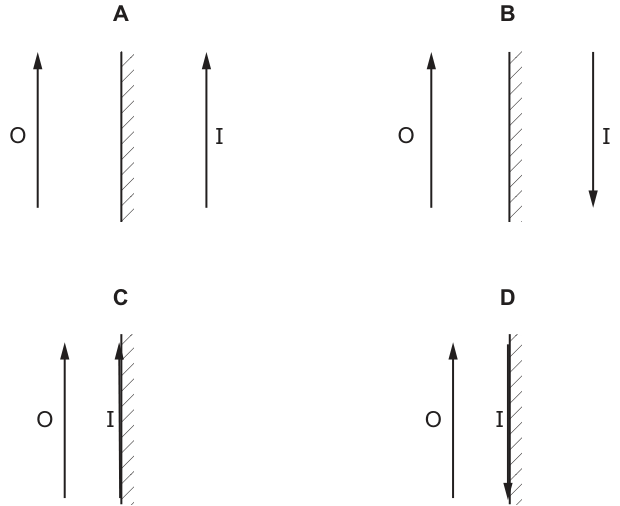
An object O is placed in front of a plane mirror.
Which diagram shows the image I formed by the mirror?
Options
Answer
A
A
Walkthrough
The image formed by a plane mirror has four key properties: it is virtual, upright (same orientation as the object), the same size as the object, and located at the same distance behind the mirror as the object is in front of it.
- Diagram A shows the image upright, the same size as the object, and at the same distance behind the mirror. This matches all properties.
- Diagram B shows the image inverted (pointing downwards). Plane mirrors do not invert images top-to-bottom.
- Diagram C shows the image touching the mirror and inverted. Both the distance and orientation are wrong.
- Diagram D shows the image touching the mirror. The distance is wrong; the image must be behind the mirror at the same distance as the object is in front.
Therefore, diagram A is correct.
Key Takeaways
- Plane mirror images are always upright, not inverted top-to-bottom.
- The image is the same size as the object.
- The image is located exactly as far behind the mirror as the object is in front of it.
Common Mistakes
- Assuming plane mirrors invert images top-to-bottom (like a real image from a converging lens or concave mirror). Plane mirrors only laterally invert (swap left and right), which is not visible for a symmetric upward-pointing arrow.
- Placing the image at the mirror surface instead of at the equal distance behind it.
Things to Be Careful About
- Lateral inversion vs top-bottom inversion: A plane mirror swaps left and right, but not top and bottom. For an asymmetric object (e.g., an arrow pointing right), the image would point left. For a symmetric upward arrow, the image simply points up.
- Always check both the orientation and the distance of the image relative to the mirror.
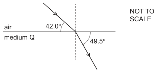
The diagram shows a ray of light travelling from air to medium Q.
What is the critical angle for the boundary between medium Q and air?
Options
A
B
C
D
Working
The angle of incidence is measured from the normal. The incident ray makes an angle of with the boundary, so:
The angle of refraction is also measured from the normal. The refracted ray makes an angle of with the boundary, so:
Using Snell's law, the refractive index of medium Q (relative to air) is:
The critical angle is given by :
Answer
C
C
Walkthrough
-
Identify the angles of incidence and refraction. In optics, angles are always measured from the normal (the dashed line perpendicular to the boundary), not from the boundary surface itself. The diagram gives the angle between the incident ray and the boundary as , so the angle of incidence is . Similarly, the angle between the refracted ray and the boundary is , so the angle of refraction is .
-
Calculate the refractive index. Light is bending towards the normal as it enters medium Q (), which means medium Q is optically denser than air. We can find the refractive index of medium Q using Snell's law:
- Calculate the critical angle. The critical angle is the angle of incidence in the denser medium (medium Q) for which the angle of refraction in the less dense medium (air) is . The formula is . Substituting the value of :
This matches option C.
Key Takeaways
- Angles are measured from the normal: Always subtract the given angle (if measured from the surface) from to get the angle of incidence or refraction.
- Refractive index and critical angle: The refractive index can be found from the ratio of sines of angles, and the critical angle is found using .
- Direction of bending: Light bending towards the normal indicates entering a denser medium, which is a prerequisite for total internal reflection and a critical angle to exist when light tries to exit back into the less dense medium.
Common Mistakes
- Using angles from the boundary directly: A common error is to use and directly in Snell's law. This gives an incorrect refractive index and a wrong critical angle.
- Wrong critical angle formula: Some students might try to use or forget to take the reciprocal. Remember only when going from the medium to air (or vacuum).
- Confusing the direction of light: The critical angle is only defined for light travelling from a denser medium to a less dense medium. Here, light must travel from Q to air. The calculation correctly captures this because for air to Q, so .
Things to Be Careful About
- Read the diagram carefully: The angles and are marked between the rays and the horizontal boundary line, not the vertical normal. Always check where the arc is drawn.
- Significant figures: The given angles are to 1 decimal place. The final answer should be given to 1 decimal place as well (), matching the options.
- Unit consistency: Angles are in degrees, ensure your calculator is in degree mode when calculating sines and inverse sines.
Which two waves are components of the electromagnetic spectrum?
Options
A light and sound
B ultrasound and ultraviolet
C water waves and infrared
D X-rays and microwaves
Working
The electromagnetic spectrum includes radio waves, microwaves, infrared, visible light, ultraviolet, X-rays and gamma rays.
- A: light is electromagnetic, but sound is a mechanical wave.
- B: ultraviolet is electromagnetic, but ultrasound is a sound wave.
- C: infrared is electromagnetic, but water waves are mechanical.
- D: X-rays and microwaves are both electromagnetic waves.
Answer
D
D
Walkthrough
This question tests whether you can pick out the two waves that belong to the electromagnetic spectrum. The electromagnetic spectrum is the full range of electromagnetic waves, from radio waves to gamma rays. The main regions, in order of increasing frequency, are:
radio waves, microwaves, infrared, visible light, ultraviolet, X-rays, gamma rays.
Now check each option:
- A says light and sound. Light is electromagnetic, but sound is a mechanical wave that needs a medium such as air to travel through.
- B says ultrasound and ultraviolet. Ultraviolet is electromagnetic, but ultrasound is a sound wave, not an electromagnetic wave.
- C says water waves and infrared. Infrared is electromagnetic, but water waves are mechanical waves moving on the surface of water.
- D says X-rays and microwaves. Both are part of the electromagnetic spectrum, so this is the correct answer.
Key Takeaways
- Memorise the main regions of the electromagnetic spectrum: radio, microwaves, infrared, visible, ultraviolet, X-rays, gamma rays.
- Electromagnetic waves can travel through empty space.
- Sound waves and water waves are mechanical waves, so they are not part of the electromagnetic spectrum.
Common Mistakes
- Confusing ultrasound with ultraviolet. Ultrasound is a sound wave; ultraviolet is an electromagnetic wave.
- Assuming that any wave is electromagnetic. Sound and water waves are mechanical and need a medium to travel through.
Things to Be Careful About
- Remember that the electromagnetic spectrum includes only electromagnetic waves, not sound waves or water waves.
- When a question asks for two components, check both parts of the option before choosing it.
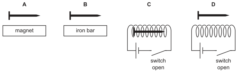
The diagrams show an iron nail in four different situations.
In which diagram is the nail an induced magnet?
Options
Answer
A
A
Walkthrough
Induced magnetism occurs when an unmagnetised magnetic material, such as an iron nail, is placed in an external magnetic field. The field causes the domains in the iron to align, turning the nail into a temporary magnet.
- Diagram A: The iron nail is placed directly above a permanent bar magnet. The permanent magnet produces a magnetic field, which acts on the nail and induces magnetism in it.
- Diagram B: The iron nail is placed above an unmagnetised iron bar. Because the bar is not magnetised, there is no external magnetic field to induce magnetism in the nail.
- Diagram C: The iron nail is above a solenoid, but the switch is open. With the switch open, no current flows through the coil, so the solenoid produces no magnetic field. The nail remains unmagnetised.
- Diagram D: The iron nail is inside a solenoid, but again the switch is open. No current means no magnetic field, so no induced magnetism occurs.
Therefore, the nail is only an induced magnet in diagram A.
Key Takeaways
- Induced magnetism requires an external magnetic field to align the magnetic domains in a magnetic material.
- Permanent magnets and current-carrying coils (with closed switches) provide the necessary magnetic field; unmagnetised materials and open circuits do not.
Common Mistakes
- Assuming that being near any metal object (like the iron bar in B) will cause induced magnetism, forgetting that the external object must itself be magnetic.
- Forgetting to check the state of the switch in the solenoid diagrams (C and D); an open switch means no current and no magnetic field.
Things to Be Careful About
- Remember that induced magnets are temporary: they lose their magnetism once removed from the external magnetic field.
- Always check both the nature of the external object (permanent magnet vs. unmagnetised material) and the circuit state (switch closed vs. open) when evaluating magnetic field sources.
Which row correctly shows a magnetic metal and a non-magnetic metal?
Options
| magnetic metal | non-magnetic metal | |
|---|---|---|
| A | aluminium | copper |
| B | copper | steel |
| C | iron | copper |
| D | steel | iron |
Working
Iron and steel are magnetic metals. Copper and aluminium are non-magnetic metals.
- A: aluminium is not a magnetic metal, so A is wrong.
- B: copper is not magnetic and steel is magnetic, so B is wrong.
- C: iron is magnetic and copper is non-magnetic, so C is correct.
- D: steel and iron are both magnetic, so D is wrong.
Answer
C
C
Walkthrough
This question asks you to choose the row that correctly pairs a magnetic metal with a non-magnetic metal. A magnetic metal is one that is attracted to a magnet, such as iron, nickel and cobalt. Steel contains mostly iron, so steel is also magnetic. Copper and aluminium are not attracted to a magnet, so they are non-magnetic metals.
Look at each option:
- A: aluminium is not magnetic, so this row is already wrong.
- B: copper is not magnetic and steel is magnetic, so the two labels are swapped.
- C: iron is magnetic and copper is non-magnetic, so this row is correct.
- D: steel and iron are both magnetic, so the second label is wrong.
Therefore the correct answer is C.
Key Takeaways
- Common magnetic metals include iron, nickel, cobalt and steel.
- Common non-magnetic metals include copper, aluminium, gold and silver.
- A magnetic material is attracted to a magnet; a non-magnetic material is not.
Common Mistakes
- Thinking that all metals are magnetic. Copper and aluminium are metals but they are not attracted to magnets.
- Thinking that steel is non-magnetic. Steel contains iron, so it is magnetic.
- Confusing iron with copper when recalling examples of magnetic metals.
Things to Be Careful About
- The question asks for a magnetic metal and a non-magnetic metal, so both parts of the row must be correct.
- Steel is an alloy that behaves as a magnetic material because of the iron it contains.
- Aluminium is a metal, but it is not magnetic, so it cannot be the magnetic metal in any correct row.
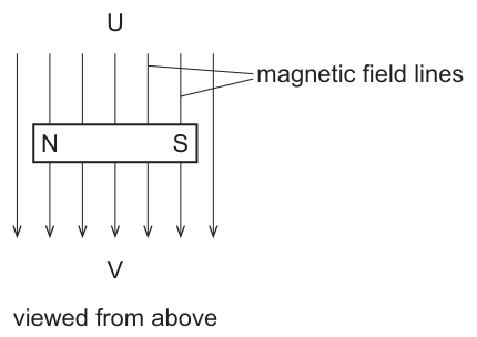
A freely suspended magnet is held perpendicular to a uniform magnetic field as shown. The magnet is viewed from above.
What happens to the magnet when it is released?
Options
A It turns through 90° clockwise and then stops moving.
B It turns through 90° anticlockwise and then stops moving.
C It turns through 90° clockwise and moves towards U.
D It turns through 90° anticlockwise and moves towards V.
Working
The north pole of a freely suspended magnet aligns with the direction of the external magnetic field. The field lines point from U to V (downwards in the diagram). Currently, the north pole (N) is on the left and the south pole (S) is on the right. To align with the field, the N pole must turn towards V (downwards) and the S pole must turn towards U (upwards). This rotation is anticlockwise.
Since the magnetic field is uniform, the force on the N pole is equal in magnitude and opposite in direction to the force on the S pole. These forces produce a turning effect (a couple) but no resultant translational force. Therefore, the magnet will not move towards U or V.
The magnet turns through 90° anticlockwise and then stops moving.
Answer
B
B
Walkthrough
- Direction of the magnetic field: The diagram shows magnetic field lines directed from U to V. In the plane of the page, this is downwards.
- Alignment of the magnet: A freely suspended magnet will rotate until its north pole points in the direction of the magnetic field lines. Currently, the N pole is on the left and the S pole is on the right. For the N pole to point downwards (towards V), it must move to the right and down, while the S pole must move to the left and up. Viewed from above, this is an anticlockwise rotation of 90°.
- Translational motion: A common misconception is that the magnet will be pulled towards one end of the field. However, in a uniform magnetic field, the force on the N pole (downwards) is exactly balanced by the equal and opposite force on the S pole (upwards). The resultant force is zero, so there is no net movement towards U or V. The only effect is the couple that turns the magnet.
- Conclusion: The magnet turns 90° anticlockwise and stops. This matches option B.
Key Takeaways
- A freely suspended magnet aligns its north pole with the external magnetic field.
- A uniform magnetic field exerts equal and opposite forces on the poles of a magnet, producing a turning effect (couple) but no resultant translational force.
- When determining rotation, always use the viewpoint specified (here, 'viewed from above').
Common Mistakes
- Clockwise vs anticlockwise: Choosing option A or C by misjudging the direction of rotation. Remember that the N pole must follow the field lines (downwards in this diagram), which requires an anticlockwise turn from the initial left-right orientation.
- Net translational force: Choosing option C or D by assuming the magnet will be attracted towards one side. In a uniform field, the forces on the two poles cancel out completely; there is no net pull towards U or V.
Things to Be Careful About
- Viewpoint: The question specifies 'viewed from above'. This means clockwise and anticlockwise are judged exactly as they appear on the printed diagram. If the question had said 'viewed from below', the rotation direction would be reversed.
- Uniform vs non-uniform field: If the field were non-uniform (e.g., near a single pole), there would be a resultant force and the magnet would translate as well as rotate. The word 'uniform' is the key to knowing the translation is zero.
A plastic rod becomes charged when it is rubbed with a cloth.
Which statement gives the reason for the charge on the rod?
Options
A The plastic rod loses protons and becomes negatively charged.
B The plastic rod loses electrons and becomes negatively charged.
C The plastic rod gains protons and becomes positively charged.
D The plastic rod loses electrons and becomes positively charged.
Working
When a plastic rod is rubbed with a cloth, only electrons move between them. Protons are fixed in the nucleus and are not transferred. The plastic rod becomes positively charged, which means it has lost electrons.
- A and B are wrong because the plastic rod becomes positively charged, not negatively charged.
- C is wrong because protons are not transferred during rubbing.
- D correctly states that the plastic rod loses electrons and becomes positively charged.
Answer
D
D
Walkthrough
The question tests the model of charging by friction. When two different materials are rubbed together, electrons are transferred from one material to the other. The material that gains electrons becomes negatively charged, while the material that loses electrons becomes positively charged. The key is that only electrons move; protons are tightly bound in the nucleus and do not move during rubbing.
- Option A is incorrect because it says the rod becomes negatively charged, but the rod becomes positively charged.
- Option B is incorrect for the same reason: it says the rod becomes negatively charged.
- Option C is incorrect because it says the rod gains protons, which does not happen during rubbing.
- Option D correctly identifies that the rod loses electrons and becomes positively charged.
Key Takeaways
- Charging by friction involves the transfer of electrons only.
- Loss of electrons results in a positive charge; gain of electrons results in a negative charge.
- Protons do not move during charging by friction.
Common Mistakes
- Choosing B might happen if a student thinks the rod becomes negatively charged, but the rod becomes positively charged.
- Choosing C might happen if a student forgets that protons do not move during rubbing.
Things to Be Careful About
- Remember that the rod becomes positively charged, so it must have lost electrons.
- The direction of electron transfer determines the sign of the charge on each object.
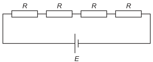
Four resistors, each of resistance , are connected in series with a cell of e.m.f. .
From left to right, what is the current in each of the resistors?
Options
A
B
C
D
Working
Total resistance of four identical resistors in series: .
Using Ohm's law, the current supplied by the cell is .
In a series circuit, the current is the same at every point. Therefore, the current through each of the four resistors is .
Answer
A
A
Walkthrough
- Identify the circuit configuration: The diagram shows four resistors, each of resistance , connected end-to-end in a single loop with a cell of e.m.f. . This is a series circuit.
- Calculate total resistance: For resistors in series, the total resistance is the sum of the individual resistances. .
- Calculate the circuit current: Apply Ohm's law using the total e.m.f. and total resistance: .
- Determine current in each resistor: A fundamental rule of series circuits is that the current is the same at every point. Charge is not 'used up' as it flows through the components. Thus, the current through each individual resistor is also .
- Select the correct option: Option A correctly lists for all four resistors from left to right.
Key Takeaways
- Series resistance: Resistors in series add together ().
- Current in series: The current is identical everywhere in a series circuit. It does not decrease as it passes through components.
- Ohm's law: The total current in a circuit is given by .
Common Mistakes
- Current is 'used up': A common misconception is that current decreases after passing through each resistor, leading to choices like B or C. Current is a rate of flow of charge; charge is conserved, so the current must be the same throughout the loop.
- Ignoring resistors: Forgetting to add all four resistances and simply using leads to option D.
Things to Be Careful About
- Current vs. potential difference: While the current is the same everywhere in this series circuit, the potential difference (p.d.) is shared. The p.d. across each individual resistor would be . Do not confuse the current formula with the p.d. divider rule.
- Series vs. parallel: Always check the circuit diagram. If these were in parallel, the total resistance would be and the current through each would be , but the diagram clearly shows a series connection.
How can one volt also be expressed?
Options
A one coulomb per ampere
B one coulomb per joule
C one joule per ampere
D one joule per coulomb
Working
One volt is the potential difference that transfers one joule of energy to each coulomb of charge that passes.
So one volt is one joule per coulomb.
Answer
D
D
Walkthrough
Voltage, or potential difference, is the energy transferred per unit charge. In equation form,
where is the potential difference in volts, is the energy transferred in joules and is the charge in coulombs.
If and , then . Therefore one volt is the same as one joule per coulomb.
Look at each option:
- A one coulomb per ampere is a unit of time, because .
- B one coulomb per joule is the inverse of the volt.
- C one joule per ampere is not the volt; it is a volt-second.
- D one joule per coulomb is exactly the definition of the volt.
So the correct answer is D.
Key Takeaways
- The volt is defined as the energy transferred per unit charge.
- Use to connect potential difference, energy and charge.
- The unit of potential difference is the joule per coulomb.
Common Mistakes
- Choosing B by inverting the relationship: remember it is joule per coulomb, not coulomb per joule.
- Confusing potential difference with power: power is energy per unit time, not energy per unit charge.
- Thinking that current, not charge, appears in the definition of the volt.
Things to Be Careful About
- Always write the unit correctly: the volt is .
- Distinguish between charge (, in coulombs) and current (, in amperes).
- The equation is the key link for this definition.
X is a piece of wire with length , area and resistance .
Wire Y is made from the same material and is connected to wire X to produce a component with a total resistance of .
What are the dimensions of Y and how is it connected to X?
Options
| length | area | connection | |
|---|---|---|---|
| A | in parallel | ||
| B | in series | ||
| C | in parallel | ||
| D | in series |
Working
The resistance of a wire is proportional to its length and inversely proportional to its cross-sectional area:
The total resistance is smaller than , so Y must be connected in parallel with X. (A series connection would give a total resistance greater than .)
For two resistors in parallel:
So .
Check option C: . ✓
Answer
C
C
Walkthrough
The key physics here is the formula for the resistance of a wire: , where is the resistivity (a property of the material), is the length and is the cross-sectional area. Doubling the length doubles the resistance; doubling the area halves it.
First, decide the connection. The total resistance must be , which is less than . When two resistors are in series, the total is the sum, which is always bigger than either one. So a series connection can never give — that rules out options B and D immediately. A parallel connection gives a total smaller than either resistor, so the connection must be parallel.
Now find what resistance Y must have. For two resistors in parallel:
We want , so:
So . Wire Y must have the same resistance as wire X. Now check which option gives a wire of resistance using :
- Option A: length , area → . Too big.
- Option C: length , area → . ✓
So C is correct.
Key Takeaways
- Resistance of a wire: — proportional to length, inversely proportional to area.
- Series connection: total (always bigger than either).
- Parallel connection: total is smaller than either resistor.
- A total smaller than one of the resistors forces a parallel connection.
Common Mistakes
- Choosing a series option: series always increases total resistance, so it can never give .
- Computing incorrectly: forgetting that area appears in the denominator, so increasing area by reduces resistance by .
- Thinking that doubling length halves resistance — it doubles it.
Things to Be Careful About
- The connection decision comes first: total means parallel.
- When checking options, compute for each and compare with .
- Only the ratio matters — the material is the same, so cancels.
Which circuit contains a fuse and a diode?
Options
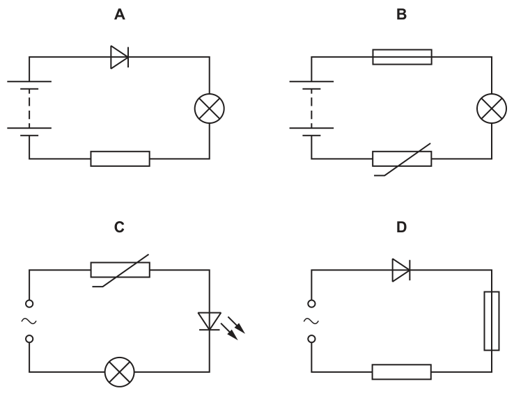
Answer
D
Circuit D is the only one containing both a diode (triangle with a bar) and a fuse (rectangle with a wire passing through it). Circuit A has a diode but no fuse. Circuit B has neither. Circuit C has an LED (a light-emitting diode) but no fuse.
D
Walkthrough
We need to find the circuit that contains both a fuse and a diode. Let us examine the symbols in each option:
- Circuit A: Contains a d.c. battery, a diode (triangle with a vertical bar), a lamp (circle with a cross), and a fixed resistor (rectangle). There is no fuse.
- Circuit B: Contains a d.c. battery, a fixed resistor, a lamp, and a thermistor (rectangle with a diagonal arrow through it). There is no diode and no fuse.
- Circuit C: Contains an a.c. power supply (circle with a tilde), a thermistor, an LED (diode symbol with two arrows pointing away indicating light emission), and a lamp. While an LED is a type of diode, there is no fuse in this circuit.
- Circuit D: Contains an a.c. power supply, a diode (triangle with a vertical bar), a fixed resistor (rectangle on the right), and a fuse (rectangle at the bottom with a wire passing through it). This circuit contains both a diode and a fuse.
Therefore, D is the correct answer.
Key Takeaways
- Recognise the standard circuit symbol for a fuse: a rectangle with a line passing through it.
- Recognise the standard circuit symbol for a diode: a triangle pointing towards a vertical bar.
- Distinguish between a fixed resistor (rectangle only) and a fuse (rectangle with a line through it).
- Note that an LED is a diode that emits light, but in multiple-choice questions asking for "a diode", a standard rectifier diode is usually intended, and the presence of the fuse is the key differentiator here.
Common Mistakes
- Confusing the fuse symbol with a fixed resistor. A fixed resistor is just a rectangle; a fuse is a rectangle with a wire passing through it.
- Thinking an LED is not a diode. While technically it is, circuit C lacks a fuse, so it cannot be the answer.
- Overlooking the a.c. vs d.c. source, though this is not required to answer the question.
Things to Be Careful About
- Always check for the specific symbols requested. The fuse symbol is often drawn as a small rectangle with a line through it, which can look like a resistor if not looked at carefully.
- In circuit diagrams, components are sometimes drawn in different orientations; look for the symbol itself rather than its position.
How is energy transferred within a kettle that is powered by the mains supply?
Options
A by electrical work done to chemical energy
B by electrical work done to thermal energy
C by mechanical work done to chemical energy
D by mechanical work done to thermal energy
Working
The kettle is powered by the mains supply, so the energy is transferred as electrical work. Inside the kettle, the heating element transfers this energy to the water as thermal energy.
Chemical energy is not involved, and the kettle does no mechanical work.
Answer
B
B
Walkthrough
The question asks how energy is transferred in a kettle powered by the mains supply. The mains supply provides electrical energy. In the kettle, this electrical energy is transferred to the heating element, which then transfers it to the water as thermal energy. This is an electrical work done to thermal energy transfer.
Option A is wrong because chemical energy is not involved when a kettle is connected to the mains. Options C and D are wrong because the kettle does not use mechanical work — mechanical work involves forces moving objects, such as lifting or pushing.
Key Takeaways
- Energy can be transferred from one type to another.
- An electric kettle transfers electrical energy to thermal energy.
- "Electrical work" means energy transferred by an electric current.
- Chemical energy would come from a fuel or a battery, not from the mains supply.
Common Mistakes
- Choosing A: chemical energy is not involved in a mains-powered kettle.
- Choosing C or D: no mechanical work is done in a kettle.
- Confusing electrical work with mechanical work — electrical energy is supplied by the mains, not by moving parts.
Things to Be Careful About
- The word "mains" tells you the energy starts as electrical energy.
- The final useful energy is thermal energy, because the kettle heats water.
- "Work done" is a way of transferring energy, so "electrical work done" means energy transferred by electricity.
A magnet moves through a coil of wire as shown.
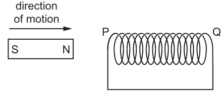
Magnetic poles are produced at the two ends of the coil as the magnet enters and as the magnet leaves the coil.
Which pole is induced at P when the magnet enters the coil and which pole is induced at Q when the magnet leaves the coil?
Options
| pole at P when magnet enters the coil | pole at Q when magnet leaves the coil | |
|---|---|---|
| A | N | N |
| B | N | S |
| C | S | N |
| D | S | S |
Working
When the magnet enters the coil (N pole leading into end P):
The north pole of the magnet is moving toward end P of the coil. By Lenz's law, the induced current must oppose this change. The coil therefore induces a north pole at P to repel the approaching north pole.
Pole at P = N.
When the magnet leaves the coil (S pole receding from end Q):
The south pole of the magnet is moving away from end Q. By Lenz's law, the induced current must oppose this change. The coil therefore induces a north pole at Q to attract the receding south pole.
Pole at Q = N.
Both induced poles are N.
Checking the options:
- A: P = N, Q = N ✓
- B: P = N, Q = S ✗
- C: P = S, Q = N ✗
- D: P = S, Q = S ✗
Answer
A
A
Walkthrough
A bar magnet with its south pole on the left and north pole on the right is moving to the right into a coil. The coil has its left end labelled P and its right end labelled Q.
Step 1 — Magnet entering (N pole approaching P):
As the north pole of the magnet moves toward end P, the magnetic flux through the coil increases. By Lenz's law, the induced current flows in a direction that opposes the change causing it. To oppose the approaching north pole, end P must become a north pole (like poles repel). This is the 5054 qualitative route — no flux equations needed, just the rule "induced pole opposes the change."
So the pole induced at P when the magnet enters is N.
Step 2 — Magnet leaving (S pole receding from Q):
As the south pole of the magnet moves away from end Q, the magnetic flux through the coil decreases. Lenz's law says the induced current opposes this decrease. To oppose the receding south pole, end Q must become a north pole (unlike poles attract, so the coil pulls the departing south pole back).
So the pole induced at Q when the magnet leaves is N.
Step 3 — Match to the options:
P = N and Q = N corresponds to option A.
Key Takeaways
- When a magnet approaches a coil, the near end of the coil becomes the same pole as the approaching magnet pole (to repel it).
- When a magnet leaves a coil, the near end of the coil becomes the opposite pole to the departing magnet pole (to attract it and oppose the loss of flux).
- This is the qualitative form of Lenz's law used at O Level: the induced effect always opposes the change that causes it.
Common Mistakes
- Choosing S at P (option C or D): confusing the rule and thinking the coil "follows" the magnet instead of opposing it. The coil repels an approaching pole and attracts a departing pole.
- Choosing S at Q (option B): correctly identifying P but forgetting that when the south pole leaves, the coil induces a north pole at Q to attract it back.
- Thinking the coil always produces the same pole at both ends: the induced polarity depends on whether the magnet is entering or leaving, so P and Q can (and do) have the same or different poles depending on the situation.
Things to Be Careful About
- Always identify which pole of the magnet is leading and which is trailing. Here the north pole enters first (right side of magnet, moving right), and the south pole leaves last.
- Remember the two separate cases: entry (approach → repel → same pole) and exit (departure → attract → opposite pole). Mixing these up is the most common error.
- At 5054, Lenz's law is applied qualitatively — no need to determine current direction or use the right-hand grip rule unless asked. The pole argument is sufficient and is the expected route.
A straight vertical wire carries a current in the direction shown.
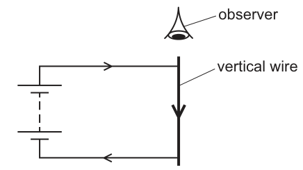
What is the pattern of the magnetic field around the wire seen by an observer viewing the wire from the position shown?
Options
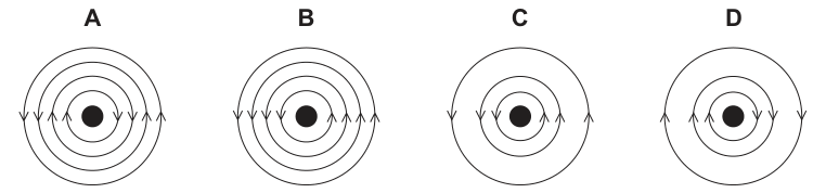
Working
-
Field direction: The current in the vertical wire flows downwards (away from the observer looking from above). Using the right-hand grip rule with the thumb pointing downwards (into the page), the curled fingers point in a clockwise direction. Looking at the options:
- In A and D, the left-side arrows point upwards and the right-side arrows point downwards, which corresponds to a clockwise circular field.
- In B and C, the left-side arrows point downwards and the right-side arrows point upwards, which corresponds to an anticlockwise circular field.
-
Field strength and spacing: The magnetic field is strongest near the wire and becomes weaker with increasing distance. Therefore, the field lines must be closer together near the centre and spread further apart as distance from the wire increases. Diagram D shows increasing line spacing with distance, whereas A shows equally spaced concentric circles.
Thus, D is the correct representation.
Answer
D
D
Walkthrough
To determine the correct magnetic field pattern around a straight, current-carrying wire seen by the observer:
-
Identify the direction of current from the observer's viewpoint:
The observer is positioned directly above the wire, looking downwards along its length. The arrow on the vertical wire indicates that conventional current is flowing downwards (away from the observer, or into the plane of the page). -
Determine the direction of the magnetic field:
Using the right-hand grip rule (also known as the right-hand corkscrew rule):- Point the thumb of your right hand in the direction of conventional current (downwards / into the page).
- The fingers curl around the wire in the direction of the magnetic field lines.
- Curled fingers indicate a clockwise direction around the wire.
- Looking at the vertical arrows on the diagrams:
- Clockwise field: upward arrow on the left side, downward arrow on the right side (seen in A and D).
- Anticlockwise field: downward arrow on the left side, upward arrow on the right side (seen in B and C).
-
Determine the spacing of the magnetic field lines:
- The strength of the magnetic field around a long straight wire is inversely proportional to the distance from the wire ().
- Closer to the wire, the field is stronger, represented by field lines packed closely together.
- Further from the wire, the field is weaker, represented by field lines spaced further apart.
- In diagram D, the spacing between successive concentric circles increases as radius increases. In diagram A, the circles are equally spaced.
Combining both features (clockwise direction and increasing spacing with distance), diagram D is correct.
Key Takeaways
- The magnetic field around a straight current-carrying wire forms concentric circles centred on the wire.
- The direction of the magnetic field is given by the right-hand grip rule (thumb in direction of current, curled fingers in direction of field lines).
- Magnetic field line spacing represents field strength: closer lines mean a stronger field, wider spacing means a weaker field.
Common Mistakes
- Using the left hand instead of the right hand, which inverts the field direction to anticlockwise.
- Forgetting that field strength decreases with distance from the wire, leading to the selection of uniformly spaced circles (A).
- Misinterpreting the arrow directions on the concentric rings (e.g. reading up on the left and down on the right as anticlockwise rather than clockwise).
Things to Be Careful About
- Ensure you identify the observer's viewpoint correctly: looking from the top means downwards current is flowing away from the observer.
Which part of a simple d.c. motor reverses the direction of current in the coil once every half rotation of the coil?
Options
A the armature
B the brushes
C the slip rings
D the split-ring commutator
Working
In a simple d.c. motor, the split-ring commutator reverses the direction of the current in the coil every half rotation. This keeps the turning effect in the same direction so the coil continues to rotate.
Answer
D
D
Walkthrough
This question asks which part of a simple d.c. motor reverses the current in the coil once every half rotation.
The coil of a d.c. motor is connected to the external circuit through a split-ring commutator. As the coil rotates, the split ring also rotates. After half a turn, the two halves of the ring swap contact with the two brushes, so the current in the coil reverses direction. This reversal happens once every half rotation, which keeps the coil turning in the same direction.
The armature is the rotating coil itself, not the part that reverses the current. The brushes are fixed contacts that press against the commutator; they do not reverse the current. Slip rings are used in an a.c. generator to keep a continuous connection without reversing the current, so they are not correct here.
Therefore, the correct answer is D, the split-ring commutator.
Key Takeaways
- The split-ring commutator reverses the current in the coil every half turn.
- This reversal is what allows the coil of a d.c. motor to keep rotating in one direction.
- Slip rings are used for a.c. generators, not for a d.c. motor.
Common Mistakes
- Choosing C (slip rings): slip rings do not reverse the current; they are used in a.c. generators.
- Choosing A (armature): the armature is the rotating coil, not the reversing device.
- Choosing B (brushes): brushes only make electrical contact with the rotating commutator.
Things to Be Careful About
- Remember the difference between a split-ring commutator and slip rings.
- The phrase "once every half rotation" is the key clue pointing to the split-ring commutator.
Which statement about the nuclide notation is correct?
Options
A is the nucleon number which is different for different isotopes of .
B is the proton number which is the same for different isotopes of .
C is the nucleon number which is the same for different isotopes of .
D is the proton number which is different for different isotopes of .
Working
In , the superscript is the nucleon number (protons + neutrons) and the subscript is the proton number.
Isotopes of the same element have the same proton number but different numbers of neutrons, so their nucleon numbers are different.
- A is correct: is the nucleon number, and it differs between isotopes.
- B is wrong: is not the proton number.
- C is wrong: is not the nucleon number.
- D is wrong: is the proton number, which is the same for isotopes.
Answer
A
A
Walkthrough
In the notation , the number at the top is the nucleon number: the total number of protons and neutrons in the nucleus. The number at the bottom is the proton number: the number of protons alone.
Isotopes are atoms of the same element with the same number of protons but different numbers of neutrons. Therefore all isotopes of have the same , while they can have different values.
Check each option:
- A says is the nucleon number and is different for different isotopes. Both parts are correct.
- B says is the proton number, which is wrong.
- C says is the nucleon number, which is wrong.
- D says is the proton number but different for different isotopes, which is wrong because the proton number is the same for all isotopes of the same element.
So the only correct statement is A.
Key Takeaways
- In , the superscript is the nucleon number and the subscript is the proton number.
- Isotopes have the same proton number but different nucleon numbers.
- The proton number identifies the element.
Common Mistakes
- Confusing the superscript and subscript positions in nuclide notation.
- Thinking isotopes have different proton numbers; they have different numbers of neutrons.
- Using the terms nucleon number and proton number interchangeably.
Things to Be Careful About
- Always read the top number as the nucleon number and the bottom number as the proton number.
- The element symbol is identified by , not by .
- For isotopes, stays the same and changes, exactly as statement A says.
During a radioactivity experiment, the background reading is .
A radioactive source is placed in front of a detector which is connected to a counter.
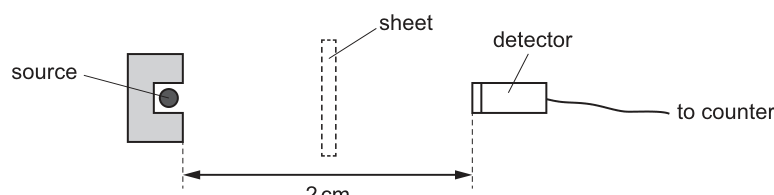
Counter readings are taken with and without sheets of different materials placed between the source and the detector.
| type of sheet | reading / counts per minute |
|---|---|
| no sheet | 750 |
| thin card | 750 |
| thick aluminium | 478 |
Which types of radiation are being emitted by the source?
Options
A alpha particles, beta particles and gamma rays
B alpha particles and beta particles only
C alpha particles and gamma rays only
D beta particles and gamma rays only
Working
The background reading is . Subtract this from each reading to find the count rate due to the source alone:
- No sheet:
- Thin card:
- aluminium:
Thin card: A thin sheet of card completely absorbs alpha particles. Since the count rate did not decrease when the card was inserted (), no alpha particles are being emitted. (Alpha particles would also be absorbed by the of air between the source and detector.)
Aluminium: The count rate drops from to when of aluminium is inserted. Beta particles are stopped by a few millimetres of aluminium, while gamma rays are only partially absorbed. The decrease in count rate shows that beta particles are present and are being absorbed by the aluminium. The count rate remains well above background (), showing that gamma rays are also present and passing through the aluminium.
The source emits beta particles and gamma rays only.
Answer
D
D
Walkthrough
-
Subtract background radiation: The counter always records background radiation from cosmic rays and naturally radioactive materials in the environment. This must be subtracted from every reading to isolate the radiation from the source.
- Source count rate (no sheet)
- Source count rate (thin card)
- Source count rate (aluminium)
-
Test for alpha particles: Alpha particles are strongly ionising but have very low penetrating power. They are stopped by a few centimetres of air or a thin sheet of paper/card. Here, the source is from the detector, so any alpha particles would be absorbed by the air alone. Furthermore, the thin card would definitely stop them. Since the count rate did not change when the card was inserted (), there are no alpha particles in the emission.
-
Test for beta particles: Beta particles have moderate penetrating power. They pass through thin card (count rate unchanged) but are stopped by a few millimetres of aluminium. The count rate dropped significantly when the aluminium was inserted (), indicating that beta particles were present and were absorbed by the aluminium.
-
Test for gamma rays: Gamma rays have high penetrating power. They pass through card and aluminium, though thick aluminium will reduce their intensity. The count rate did not fall to the background level () after the aluminium was inserted, meaning some radiation is still getting through. This remaining radiation is gamma rays.
Conclusion: The source emits beta particles and gamma rays only.
Key Takeaways
- Always subtract background radiation from counter readings to find the true source activity.
- Alpha particles are stopped by thin card (and air over short distances).
- Beta particles pass through thin card but are stopped by a few mm of aluminium.
- Gamma rays pass through thin card and are only partially absorbed by thick aluminium; the count rate remains above background.
Common Mistakes
- Forgetting to subtract background radiation: If a candidate uses the raw table values () without subtracting , the logic still holds for the differences, but it is a bad habit and can lead to errors if the background were different for different readings or if the final reading was close to background.
- Misidentifying the absorber effects: Confusing the penetration power of alpha, beta and gamma. For example, thinking that thin card stops beta or that aluminium stops gamma completely.
- Ignoring the air gap: Alpha particles have a range of only a few centimetres in air. At , alpha particles would likely be absorbed by the air anyway, but the thin card is the definitive test in the table.
Things to Be Careful About
- Background subtraction: The background reading is given as . This must be subtracted from all readings. , not .
- Reading the table carefully: The table shows the reading with thin card is the same as no sheet (). This is the key piece of evidence that alpha is absent. If it had dropped (e.g., to ), alpha would be present.
- Partial absorption: Gamma rays are never completely stopped by a reasonable thickness of aluminium in these experiments; the count rate drops but stays above background. The candidate must recognise that a drop from to means something was stopped (beta) and something is still getting through (gamma).
A radioactive isotope is injected into a patient as part of a medical test. The radiation emitted is detected outside the body.
What are suitable properties for this isotope?
Options
| radiation type | half-life | |
|---|---|---|
| A | alpha particles | a few hours |
| B | beta particles | a few years |
| C | gamma rays | a few hours |
| D | gamma rays | a few years |
Working
The radiation must pass through the patient's body to be detected outside, so it must be highly penetrating. Alpha particles are stopped by a few cm of air or skin, and beta particles are stopped by a few mm of metal or several cm of body tissue, so neither would be detected outside the body. Gamma rays are very penetrating and pass through the body, so they can be detected outside.
The half-life must be long enough for the test to be carried out, but short enough that the patient does not remain radioactive for a long time. A few hours is suitable; a few years would leave the patient radioactive far too long.
Answer
C
C
Walkthrough
This question asks for two properties of a radioactive isotope used in a medical test where the radiation is detected outside the body. Two separate requirements must both be satisfied.
Requirement 1 — the radiation must reach the detector outside the body.
The radiation is emitted inside the patient and must travel through body tissue before it can be detected. Alpha particles are the least penetrating — a few centimetres of air, or even a sheet of paper or the outer layer of skin, stops them completely. Beta particles penetrate further but are still stopped by a few millimetres of aluminium or a few centimetres of body tissue. Only gamma rays are penetrating enough to pass through the whole body and be detected outside. So the isotope must emit gamma rays. This eliminates options A and B.
Requirement 2 — the half-life must be suitable.
A medical isotope must stay radioactive long enough for the test to be performed (so a few hours is fine), but it must not stay radioactive for a long time afterwards, or the patient would carry dangerous radiation around for years. A half-life of a few hours means the activity falls by half every few hours, so the patient is essentially safe within a day or two. A half-life of a few years means the patient remains radioactive for years — completely unsuitable. So the half-life must be a few hours. This eliminates option D.
The only option satisfying both requirements is C: gamma rays with a half-life of a few hours.
Key Takeaways
- Medical isotopes must emit radiation that can be detected outside the body, which usually means gamma rays because of their high penetrating power.
- The half-life must balance two needs: long enough to complete the test, short enough that the patient is not radioactive for long.
- Penetrating power increases in the order alpha < beta < gamma, while ionising power decreases in the same order — the two are opposite.
Common Mistakes
- Choosing alpha particles because they are "safe" — alpha is the most ionising and most damaging if inside the body, and it would not even reach the detector outside, so it fails both criteria.
- Choosing a few years thinking a longer half-life means the isotope "lasts longer" for the test — a few hours is already plenty for a medical test, and a few years is dangerously long for the patient.
- Confusing penetrating power with ionising power: gamma is the most penetrating but the least ionising.
Things to Be Careful About
- Read both columns of the table together — the correct option must satisfy both the radiation type and the half-life, not just one.
- Remember that "detected outside the body" is the key phrase: it forces the choice of gamma rays.
- The half-life is about how long the patient stays radioactive, not about how strong the radiation is at the moment of injection.
A student writes four statements about the Solar System.
- Light takes approximately to travel from the Sun to the Earth.
- The Earth takes approximately 24 hours to rotate on its axis once.
- The Moon takes approximately 1 month to orbit the Earth.
- The Sun takes approximately 365 days to orbit the Earth.
Which statements are correct?
Options
A 1 and 2
B 2, 3 and 4
C 2 and 3 only
D 3 and 4 only
Working
Statement 1 is false: light takes about 8 minutes to travel from the Sun to the Earth. is the speed of light, not a time.
Statement 2 is true: the Earth rotates once on its axis in about 24 hours.
Statement 3 is true: the Moon orbits the Earth in about 1 month.
Statement 4 is false: the Earth orbits the Sun in about 365 days; the Sun does not orbit the Earth.
Answer
C
C
Walkthrough
This question asks you to check four statements about the Solar System and then choose the option that lists the correct ones.
- Statement 1 says light takes seconds to travel from the Sun to the Earth. This is wrong because is the speed of light, not a time. Light actually takes about 8 minutes to travel from the Sun to the Earth.
- Statement 2 says the Earth takes about 24 hours to rotate once on its axis. This is correct: one rotation gives one day.
- Statement 3 says the Moon takes about 1 month to orbit the Earth. This is correct: the Moon's orbital period is about 27.3 days, which is roughly one month.
- Statement 4 says the Sun takes about 365 days to orbit the Earth. This is wrong: the Earth orbits the Sun in about 365 days, not the other way round.
So the correct statements are 2 and 3 only, which is option C.
Key Takeaways
- The Earth rotates on its axis once in about 24 hours, giving the day.
- The Earth orbits the Sun once in about 365 days, giving the year.
- The Moon orbits the Earth in about one month.
- The speed of light is ; it is not a time interval.
Common Mistakes
- Confusing the speed of light () with the time light takes to reach the Earth. Light takes about 8 minutes, not seconds.
- Thinking that the Sun orbits the Earth. In the Solar System, the Earth orbits the Sun.
- Choosing option A because statement 1 looks like a familiar number, without noticing the unit is wrong.
Things to Be Careful About
- Always check the units in a statement. is a speed, so writing "seconds" after it makes the statement false.
- Remember the difference between rotation (spinning on an axis) and orbit (travelling around another object).
- Read all four statements before choosing an option, because several options may contain a mixture of true and false statements.
What is never formed by the explosion of a red supergiant?
Options
A a black hole
B a neutron star
C a white dwarf
D new heavier elements
Working
A red supergiant is the final stage of a very massive star. When it explodes as a supernova, the core may collapse to form a neutron star or, if it is massive enough, a black hole. The explosion also creates new heavier elements.
A white dwarf, however, is the leftover core of a low- or medium-mass star such as the Sun, after it has passed through the red giant stage and shed its outer layers. It is not formed by the explosion of a red supergiant.
Therefore C is correct.
Answer
C
C
Walkthrough
This question is about the life cycle of stars and asks which object is never produced from a red supergiant explosion.
- A low- or medium-mass star, like the Sun, eventually becomes a red giant and then collapses into a white dwarf.
- A high-mass star becomes a red supergiant, which then explodes as a supernova.
- During the supernova explosion, the core may collapse into a neutron star.
- If the core is massive enough, it may instead collapse further to form a black hole.
- The immense energy of the explosion also fuses nuclei together to create new elements heavier than iron, so new heavier elements are definitely formed.
Therefore a white dwarf is the only option that is never produced by a red supergiant explosion.
Key Takeaways
- Red supergiant → supernova → neutron star or black hole, plus new heavier elements.
- Red giant (from a lower-mass star) → white dwarf.
- The mass of the original star determines its final fate.
Common Mistakes
- Thinking that a white dwarf can be formed in a supernova explosion. It cannot: white dwarfs come from lower-mass stars like the Sun.
- Believing every red supergiant must become a black hole. In fact, the core may become a neutron star unless it is massive enough.
- Forgetting that supernova explosions are responsible for creating elements heavier than iron.
Things to Be Careful About
- The word "never" is important: you must choose the one outcome that belongs to a different kind of star.
- Distinguish between a red giant and a red supergiant: they come from stars of very different masses.
- No calculation is needed; this is a recall question about stellar life cycles.
Your score so far
Answer a question to start scoring
Your marks add up here as you work through the paper.