Physics 5054/21 — May/June 2024
Cambridge O-Level · Theory · worked solutions for every part, with the mark scheme
Topics Energy, Work and Power · Forces · Kinematics · Kinetic Particle Model of Matter · Pressure · Momentum · +14 more
A ball is released from rest at point A and moves along a smooth track ABCDE as shown in Fig. 1.1. The ball is shown at point A and as it passes point B.
The ball is always in contact with the track and air resistance is negligible.
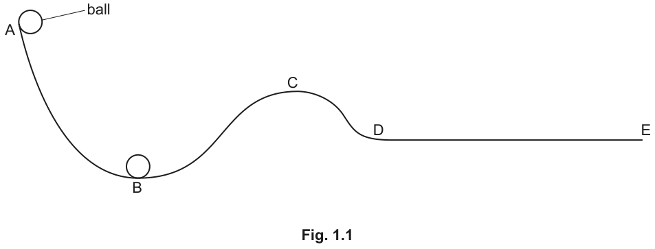
Fig. 1.2 shows the distancetime graph for the ball as it moves from A to E.
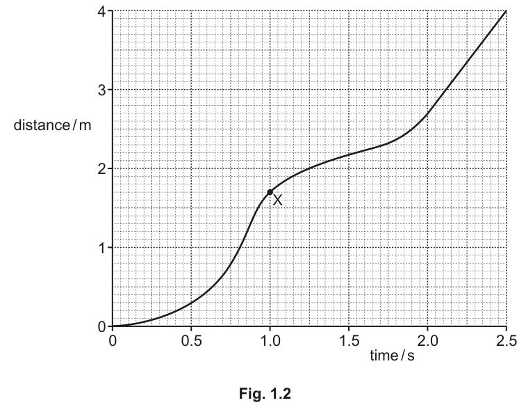
On Fig. 1.2, mark:
- with the letter P one point where the ball accelerates
- with the letter Q one point where the ball has constant speed.
Answer
- Point marked on the curve where the gradient is increasing (in the region to or to ).
- Point marked on the straight line section (between and ).
P marked between 0-0.8 s or 1.6-2.0 s; Q marked between 2.0-2.5 s
Walkthrough
On a distancetime graph:
- The gradient (slope) of the line equals the speed of the object: .
- If the graph is curved upwards (the slope becomes steeper), the speed is increasing, which means the ball is accelerating. On Fig. 1.2, this occurs from to about (as the ball rolls down from A to B) and again from about to (as it rolls down from C to D). Point can be placed anywhere in either of these regions.
- If the graph is a straight line with a constant gradient, the speed is constant. From to , the graph is a straight line, corresponding to the flat section DE of the track. Point must be placed in this region.
Key Takeaways
- Speed is given by the gradient of a distancetime graph.
- A changing gradient indicates acceleration (speeding up or slowing down).
- A straight, non-horizontal line indicates constant (uniform) speed.
Common Mistakes
- Confusing distancetime graphs with speedtime graphs (where a horizontal line means constant speed and a straight sloped line means constant acceleration).
- Placing on a horizontal part or at the inflection point instead of the straight section.
Things to Be Careful About
- Check the axes carefully: this is a distancetime graph, not a speedtime graph.
Determine the speed of the ball at point X on Fig. 1.2.
Show your working.
speed = ______
Working
Draw a tangent to the curve at point (, ).
Find the gradient of the tangent:
Using coordinates from the tangent, for example and :
Answer
2.2 m/s
Walkthrough
To find the speed at a specific instant on a curved distancetime graph, we find the gradient of the curve at that point by drawing a tangent:
- Place a ruler along the curve at point () so that it touches the curve only at without crossing it.
- Draw a long, straight tangent line extending across the grid.
- Choose two convenient points on the tangent line that lie on grid intersections, spaced well apart for accuracy.
- Calculate the gradient using:
- Any correctly calculated gradient from a properly drawn tangent within the range to is accepted.
Key Takeaways
- Instantaneous speed on a distancetime graph is found by drawing a tangent at that point and determining its gradient.
- Use a large triangle (large ) to minimise reading uncertainty.
Common Mistakes
- Calculating speed by simply dividing the coordinates of point directly () instead of drawing a tangent and finding its gradient.
- Drawing a secant (a line cutting across the curve) instead of a true tangent.
Things to Be Careful About
- Ensure the tangent line is long enough to read values accurately from the grid.
- Always include the correct unit ( is printed, so the numerical value must match).
The speeds of the ball at A, B, C and D are , , and respectively.
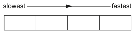
Arrange these four speeds from slowest to fastest.
Answer
v_A, v_C, v_D, v_B
Walkthrough
Since the track is smooth and air resistance is negligible, the total mechanical energy () is conserved throughout the motion:
- At point , the ball is released from rest, so its speed is zero: (slowest).
- As the ball moves down, gravitational potential energy () is converted into kinetic energy (). Lower height means lower and higher , and therefore higher speed.
- Comparing the heights of the remaining points from Fig. 1.1:
- Point is higher than and , so it has the next lowest kinetic energy and speed.
- Point is lower than but higher than .
- Point is at the lowest position on the track, where is at its minimum, so and speed are at their maximum.
Therefore, from slowest to fastest:
Key Takeaways
- In the absence of resistive forces, mechanical energy is conserved.
- Maximum height corresponds to minimum kinetic energy (and minimum speed); lowest height corresponds to maximum kinetic energy (and maximum speed).
Common Mistakes
- Forgetting that the ball is at rest at () and placing another point as the slowest.
- Misreading the relative heights of points and from the diagram.
Things to Be Careful About
- Double-check the order: the question asks from slowest to fastest (increasing speed).
Work is done to transfer energy between energy stores as the ball moves from A to B.
Name the force involved in the work done and describe the energy transfer.
Answer
- Force involved: Weight / gravity / gravitational attraction
- Energy transfer: From the gravitational potential energy store to the kinetic energy store
Force: weight (or gravity); Energy transfer: gravitational potential energy to kinetic energy
Walkthrough
- Force: As the ball moves from to , it moves downwards under the action of its weight (or gravitational force / gravity). Work is done on the ball by this downward force.
- Energy transfer:
- At point , the ball has energy in its gravitational potential energy store because of its height above the ground.
- As it rolls down to , its height decreases and its speed increases.
- The energy is transferred mechanically from the gravitational potential energy store to the kinetic energy store of the ball.
Key Takeaways
- Work is done when a force acts through a distance: .
- Falling or rolling downwards transfers energy from the gravitational potential energy store to the kinetic energy store.
Common Mistakes
- Stating the force as 'acceleration' or 'momentum' instead of 'gravity' or 'weight'.
- Describing energy without specifying the stores (e.g., just saying 'potential to movement').
Things to Be Careful About
- Ensure you identify both the starting store (gravitational potential) and the finishing store (kinetic).
The track at point B is circular in shape.
On Fig. 1.1, draw an arrow to show the direction of the resultant force on the ball at point B.
Answer
An arrow drawn at point pointing vertically upwards (towards the centre of the circular path).
Arrow pointing upwards at B
Walkthrough
At point , the track is curved upwards in a circular shape:
- An object moving along a circular path experiences an acceleration towards the centre of the circle (centripetal acceleration).
- According to Newton's second law (), the resultant force must act in the same direction as the acceleration, which is towards the centre of curvature.
- Since the curve at point is convex downwards (a trough), the centre of the circle lies directly above point .
- Therefore, the resultant force on the ball at point is directed vertically upwards (the normal contact force from the track exceeds the downward weight of the ball).
Key Takeaways
- For an object following a curved circular path, the resultant force acts towards the centre of the circular arc (centripetal force).
- At the lowest point of a dip/trough, the centre of curvature is above the object, so the resultant force acts upwards.
Common Mistakes
- Drawing the arrow downwards (confusing resultant force with weight).
- Drawing the arrow horizontally to the right (confusing force with the direction of motion/velocity).
Things to Be Careful About
- The arrow must clearly point upwards from the ball at point .
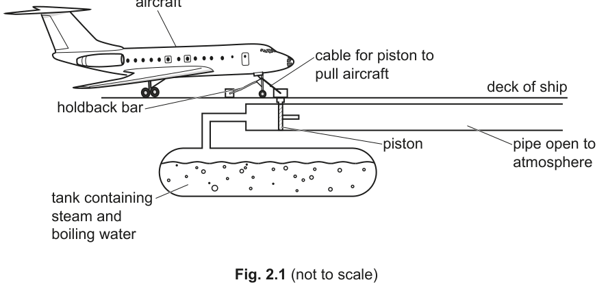
A small aircraft takes off from the horizontal deck of a ship.
Before taking off, the aircraft is held in place by a holdback bar.
When the holdback bar is released, the aircraft is pulled along the deck by a steam-powered piston as shown in Fig. 2.1.
The steam exerts a high pressure on the piston.
Answer
- Steam particles collide with the surface of the piston.
- Each collision exerts a force on the piston, and total force divided by area creates pressure (or the rate of change of momentum of colliding particles exerts a force on the area).
Steam particles collide with the piston, exerting a force over its area
Walkthrough
To explain how a gas exerts pressure according to the kinetic particle model:
- Steam consists of water molecules in rapid, random motion.
- As these particles collide with the piston face, their momentum changes as they bounce off.
- By Newton's second and third laws, each collision exerts a small force on the surface of the piston.
- Millions of such collisions occur every second across the piston's surface area. The total average force divided by the area of the piston gives the macroscopic pressure ().
Key Takeaways
- Gas pressure arises from continuous collisions of particles with the container walls/surfaces.
- Force is the rate of change of momentum during collisions, and pressure is force per unit area.
Common Mistakes
- Saying particles "push" without mentioning collisions/hitting.
- Forgetting to link the collision forces to the area to explain pressure.
Things to Be Careful About
- Ensure both essential ideas are stated: (1) particle collisions with the piston, and (2) force exerted per collision / over an area / momentum change.
Explain why the pressure on the piston increases as the temperature of the steam increases.
Answer
- The particles move faster / have higher average kinetic energy.
- They collide with the piston more frequently (more collisions per second) and with greater force / larger momentum change per collision.
Particles move faster and collide more frequently with greater force
Walkthrough
- Temperature is proportional to the average kinetic energy of the gas particles. When the temperature of the steam increases, the particles gain kinetic energy and move at higher average speeds.
- Because the particles are faster:
- They hit the piston more frequently (more collisions per second).
- Each individual collision involves a larger change in momentum, producing a larger force per collision.
- Both factors increase the total force exerted per unit area, resulting in an increased pressure.
Key Takeaways
- Higher temperature higher average kinetic energy higher particle speeds.
- Increased speed leads to both more frequent collisions and harder/more forceful collisions.
Common Mistakes
- Stating only that particles move faster without explaining how that alters collisions.
- Stating that particles expand instead of moving faster.
Things to Be Careful About
- Mention at least two distinct points: particle speed/kinetic energy increasing, and collision frequency/force per collision increasing.
When the pressure is high enough, the holdback bar is released. The steam pushes the piston along the pipe shown in Fig. 2.1.
The piston has a cross-sectional area of .
The pressure of the steam in the tank is .
Atmospheric pressure is .
Determine the resultant force on the piston caused by the pressure difference.
Show your working.
force = ______
Working
Answer
6.0 x 10^5 N
Walkthrough
- The steam pushes on one side of the piston with pressure , while atmospheric pressure opposes the motion from the open end of the pipe.
- The resultant pressure acting to move the piston is:
- Using the definition of pressure , the resultant force is:
Key Takeaways
- Resultant force from opposing pressures is calculated using the net pressure difference: .
Common Mistakes
- Forgetting to subtract atmospheric pressure and just multiplying .
- Arithmetic errors when subtracting numbers in standard form with different powers of ten (, not ).
Things to Be Careful About
- Convert powers of ten correctly: .
The force calculated in (b) causes the aircraft to accelerate to a maximum speed of from rest.
The mass of the aircraft is .
Working
Answer
8.4 x 10^5 kg m/s
Walkthrough
- State the equation for momentum:
- Substitute the given values ( and ):
Key Takeaways
- Momentum is the product of mass and velocity ().
Common Mistakes
- Squaring the velocity by confusion with kinetic energy formula .
Things to Be Careful About
- Express the answer clearly in standard form or full notation with appropriate units.
Working
Since initial speed :
Answer
1.4 s
Walkthrough
There are two equivalent ways to solve this:
Method 1: Using Impulse and Momentum
- Resultant force is the rate of change of momentum:
- The aircraft starts from rest, so initial momentum , giving .
- Rearrange for time :
Method 2: Using and
- Acceleration .
- Time .
Key Takeaways
- Impulse equals change in momentum: .
- Both momentum methods and equations of motion () lead directly to the same result.
Common Mistakes
- Using the steam force without subtracting atmospheric pressure (error carried forward from part (b) is allowed if clearly shown).
- Forgetting that the aircraft starts from rest ().
Things to Be Careful About
- Keep significant figures appropriate (2 s.f.: 1.4 s).
A pan containing ice at is placed on a gas heater as shown in Fig. 3.1.
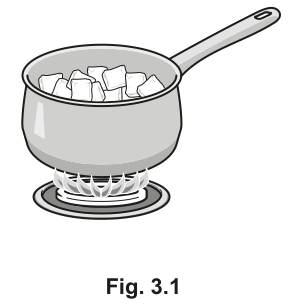
Thermal conduction occurs in the metal from which the pan is made.
By referring to particles, describe the process of thermal conduction in a metal.
Answer
Free (delocalised) electrons move from the hot area to the cold area, transferring thermal energy.
Vibrations (or collisions) between particles also pass on energy.
Free electrons move from the hot area to the cold area, transferring thermal energy; or vibrations between particles pass on energy.
Walkthrough
Thermal conduction in metals relies on two mechanisms. First, metals contain free (delocalised) electrons that can move easily. When one end of the metal is heated, these electrons gain kinetic energy and move rapidly to cooler regions, colliding with other particles and transferring energy. Second, the fixed particles in the metal lattice vibrate. Heating increases these vibrations, which are passed along the lattice through collisions with neighbouring particles. Both mechanisms transfer thermal energy from the hot end to the cold end.
Key Takeaways
Metals conduct heat well because of free electrons and particle vibrations. Conduction is the transfer of thermal energy through a material without bulk movement of the material itself.
Common Mistakes
Students often say 'heat moves' instead of 'thermal energy is transferred'. They may also forget to mention the free electrons, which are the primary reason metals are such good conductors. Saying 'particles move' is incorrect for the fixed lattice particles; they only vibrate.
Things to Be Careful About
The question asks to refer to particles. Ensure you mention both the free electrons and the vibrating particles of the metal lattice to secure both marks. Do not say 'heat rises' or 'heat moves'.
Fig. 3.2 shows how the temperature of the contents of the pan varies with time.
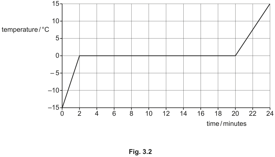
Answer
273
273
Walkthrough
The melting point of ice is 0 °C. To convert a temperature from degrees Celsius to kelvin, add 273 (or 273.15, but 273 is standard at O Level).
Key Takeaways
The Kelvin scale is an absolute temperature scale. 0 K is absolute zero. The size of one kelvin is the same as one degree Celsius. To convert from °C to K, add 273.
Common Mistakes
Forgetting to add 273, or subtracting 273 instead. Writing 'degrees kelvin' (K) instead of just 'kelvin' (K). The unit is K, not °K.
Things to Be Careful About
The mark scheme accepts 273. Using 273.15 is technically more accurate but 273 is the expected value at this level. Ensure the unit is K, not °C.
Answer
The energy supplied is used to weaken the forces between the particles (or increase their potential energy), not to increase their kinetic energy. Since temperature is a measure of average kinetic energy, it remains constant.
Energy is used to weaken the forces between particles (or increase potential energy), so kinetic energy and temperature stay constant.
Walkthrough
During melting, the substance changes state from solid to liquid. The thermal energy supplied is not used to increase the kinetic energy of the particles (which would raise the temperature). Instead, it is used as latent heat to overcome or weaken the intermolecular forces holding the particles in their fixed positions in the solid lattice. This increases the potential energy of the particles. Because the average kinetic energy of the particles does not change, the temperature remains constant until all the ice has melted.
Key Takeaways
During a change of state, temperature remains constant. The energy supplied is latent heat, which increases the potential energy of the particles by weakening or breaking the forces between them.
Common Mistakes
Saying 'the energy is used to melt the ice' without explaining what that means at the particle level. Saying 'temperature is constant because the ice is melting' is circular reasoning. Forgetting to mention that kinetic energy (and thus temperature) stays constant.
Things to Be Careful About
Use the term 'latent heat' or 'potential energy'. Do not say 'heat is used to break bonds' if the bonds are intermolecular forces, not chemical bonds. The mark scheme accepts 'weaken forces between particles' or 'more potential energy'.
The initial mass of ice in the pan is and the initial temperature is .
The specific heat capacity of ice is .
Calculate the energy required to warm the ice to its melting temperature.
energy = ______
Working
Answer
47000
47000
Walkthrough
The energy required to warm the ice is calculated using the specific heat capacity equation , where is the mass, is the specific heat capacity, and is the change in temperature.
Given:
Substituting these values:
Rounding to 2 significant figures (as the mass is given to 2 s.f.), the energy is 47000 J.
Key Takeaways
The equation calculates the thermal energy needed to change the temperature of a substance without changing its state. Ensure is the final temperature minus the initial temperature.
Common Mistakes
Forgetting to subtract a negative initial temperature (e.g., using instead of ). Using the wrong value for specific heat capacity (the value for water is 4200, but the question specifies ice).
Things to Be Careful About
The mark scheme accepts 47000 or 47250. Using 2 significant figures is appropriate here because the mass (1.5 kg) and the temperature change (15 °C) are given to 2 s.f. Always include the unit J in the final answer if asked, though the blank here implies the unit is already there.
All the energy transferred to the pan comes from the heater.
Using your answer to (iii) and Fig. 3.2, determine the power of the heater used to warm the ice.
power = ______
Working
From Fig. 3.2, the time to warm the ice is 2 minutes.
Answer
390
390
Walkthrough
Power is the rate of energy transfer, given by . From part (iii), the energy transferred to warm the ice is . From Fig. 3.2, the time taken for this warming process (from -15 °C to 0 °C) is 2 minutes. Convert this time to seconds:
Now calculate the power:
Rounding to 2 significant figures gives 390 W.
Key Takeaways
Power is energy divided by time. Always ensure time is in seconds when calculating power in watts. Reading values from a graph requires careful attention to the axis scales and units.
Common Mistakes
Forgetting to convert minutes to seconds (using gives , which is wrong). Using the energy from the wrong part of the graph. Not rounding to the correct number of significant figures.
Things to Be Careful About
The mark scheme accepts 390 or 394. Using 2 significant figures is consistent with the data given. Ensure you use the energy calculated in part (iii), not a different value. The graph clearly shows the warming phase ends at .
The graph in Fig. 3.2 has a smaller gradient when the water is liquid than when it is solid.
Suggest one reason why.
Answer
Water has a higher specific heat capacity than ice, so its temperature rises more slowly for the same rate of energy supply.
Water has a higher specific heat capacity than ice.
Walkthrough
The gradient of a temperature-time graph (with constant power input) is inversely proportional to the specific heat capacity of the substance, since , so . A smaller gradient means a larger specific heat capacity. Water has a specific heat capacity of 4200 J/(kg °C), which is roughly double that of ice (2100 J/(kg °C)). Therefore, for the same mass and the same power input, the temperature of liquid water rises more slowly than that of ice.
Key Takeaways
The gradient of a heating curve is steeper for substances with a lower specific heat capacity. Water has an unusually high specific heat capacity compared to many other substances, including its solid form, ice.
Common Mistakes
Saying 'water is denser than ice' or 'water has stronger bonds'. While water does have stronger hydrogen bonds, the direct reason for the smaller gradient is the higher specific heat capacity. The mark scheme specifically looks for 'higher specific heat capacity'.
Things to Be Careful About
The question asks for 'one reason'. Stating 'higher specific heat capacity' is sufficient and is the most direct answer. Avoid over-explaining or giving multiple reasons if only one is required, though the mark scheme accepts 'stronger bonds' as an alternative explanation for the higher specific heat capacity.
Ultrasound of frequency has a wavelength of in air.
Answer
The number of complete waves passing a given point per second.
The number of complete waves passing a given point per second.
Walkthrough
Frequency is defined as the number of complete wave cycles that pass a fixed point in one second. This is a direct recall definition from the wave properties section of the syllabus.
Key Takeaways
Frequency () is measured in hertz (Hz) and is the reciprocal of the time period (). It describes how often the wave oscillates.
Common Mistakes
Candidates sometimes say 'the number of waves per minute' or omit 'per second'. The definition must specify a time interval of one second.
Things to Be Careful About
Ensure the answer refers to 'complete waves' or 'cycles' passing a 'fixed point' or 'a point'.
Working
Answer
330
330 m/s
Walkthrough
The wave speed equation links speed (), frequency () and wavelength (): . The frequency is given as , which must be converted to standard units (Hz) by multiplying by , giving . The wavelength is . Substituting these values gives .
Key Takeaways
Always convert frequency to hertz (Hz) and wavelength to metres (m) before using to get the speed in .
Common Mistakes
Forgetting to convert to and calculating , which is wrong by a factor of .
Things to Be Careful About
The question asks for the answer in , so the unit must be included in the final answer. The mark scheme awards a C1 for the correct equation in any form and an A1 for the correct numerical answer.
Answer
Prenatal medical scanning (or sonar, cleaning, calculating depth/distance).
Prenatal medical scanning
Walkthrough
Ultrasound is used in many applications because it can travel through solids and liquids and can be reflected by boundaries between different materials. Common uses include medical imaging (scanning fetuses or internal organs), sonar for finding the depth of the sea or locating fish, ultrasonic cleaning of delicate objects, and non-destructive testing of materials.
Key Takeaways
Ultrasound has frequencies above the upper limit of human hearing () and is useful for imaging and cleaning due to its short wavelength and high energy.
Common Mistakes
Saying 'hearing' or 'music', which are uses of audible sound, not ultrasound.
Things to Be Careful About
Any valid use scores. Medical scanning, sonar, and cleaning are the most common accepted answers.
Sound waves are longitudinal waves. Water waves are transverse waves.
Describe, by referring to the movement of the particles in the wave, the difference between a longitudinal wave and a transverse wave.
You may include a labelled diagram to help your description.
Answer
In a longitudinal wave, the particles oscillate backwards and forwards in the same direction as the wave is travelling. In a transverse wave, the particles oscillate at right angles to the direction of travel of the wave.
Longitudinal: particles oscillate parallel to wave direction. Transverse: particles oscillate perpendicular to wave direction.
Walkthrough
The key difference between the two wave types lies in the direction of particle oscillation relative to the direction of energy transfer (wave travel). For longitudinal waves (like sound), particles move parallel to the wave direction, creating compressions and rarefactions. For transverse waves (like light or water waves), particles move perpendicular to the wave direction, creating crests and troughs. A labelled diagram clearly showing these oscillation directions earns the third mark.
Key Takeaways
Longitudinal = parallel oscillation; Transverse = perpendicular oscillation. Remember that the wave itself travels forward, but the particles only oscillate about a fixed position.
Common Mistakes
Saying 'particles move with the wave' — particles do not travel with the wave; they oscillate about a mean position. Confusing the direction of particle motion with the direction of wave travel.
Things to Be Careful About
The mark scheme specifically requires reference to 'the movement of the particles'. Simply saying 'sound is longitudinal and light is transverse' does not answer the question. A diagram is optional but highly recommended to secure the third mark.
Answer
An earthquake (or lightning).
Earthquake
Walkthrough
Earthquakes generate seismic waves, which include P-waves (primary waves, which are longitudinal) and S-waves (secondary waves, which are transverse). Lightning is another valid answer, as it produces thunder (sound waves, which are longitudinal) and light (electromagnetic waves, which are transverse).
Key Takeaways
Some natural events generate multiple types of waves. Seismic waves from earthquakes are a classic example of both longitudinal and transverse mechanical waves being produced.
Common Mistakes
Saying 'a speaker' (only produces longitudinal sound waves) or 'a string' (only produces transverse waves). The source must generate BOTH types.
Things to Be Careful About
Ensure the example genuinely produces both types. Earthquakes and lightning are the standard accepted answers in the mark scheme.
Fig. 4.1 shows radio waves of long and short wavelength passing over the same hill.
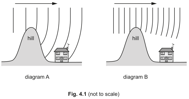
Explain why the radio waves in diagram A reach the house but the radio waves in diagram B do not reach the house.
Answer
The long wavelength radio waves in diagram A diffract (bend) significantly around the hill, reaching the house. The short wavelength radio waves in diagram B diffract very little and continue mostly straight, so they do not reach the house.
Long wavelengths diffract around the hill; short wavelengths do not diffract enough to reach the house.
Walkthrough
Diffraction is the spreading out of waves when they pass through a gap or around an obstacle. The amount of diffraction depends on the wavelength of the wave relative to the size of the obstacle or gap. When the wavelength is large compared to the obstacle, significant diffraction occurs. In diagram A, the long wavelength radio waves diffract strongly over the hill, bending down to reach the house. In diagram B, the short wavelength radio waves diffract very little, so they travel in a straight line and are blocked by the hill.
Key Takeaways
Waves diffract more when the wavelength is larger. Long radio waves (AM) can diffract around hills and buildings, while short radio waves (FM) and light waves travel in straighter lines and are blocked by obstacles.
Common Mistakes
Saying 'long waves travel faster' or 'long waves have more energy'. The speed is the same for all radio waves in air; the difference is purely due to diffraction.
Things to Be Careful About
The mark scheme awards one mark for stating that long wavelengths bend/diffract and short ones do not, and a second mark for using the term 'diffraction'. Both points must be clearly stated.
Fig. 5.1 shows part of a circuit containing a mains supply connected to a lamp and two heaters of resistance and .
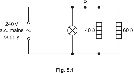
Answer
A rectangular box with a horizontal wire passing straight through its center.
Walkthrough
The question asks to complete the circuit diagram by drawing a fuse in the gap in the live wire. A fuse is a safety device designed to melt and break the circuit if the current exceeds a safe value. The standard circuit symbol for a fuse is a horizontal rectangular box (or a rectangle with a line through it) with the connecting wire passing straight through the middle horizontally.
Key Takeaways
Candidates must be able to draw and recognise standard circuit symbols, particularly the fuse, which is a critical component in mains safety circuits.
Common Mistakes
- Drawing a resistor symbol (a zig-zag line) instead of a fuse.
- Drawing the fuse symbol in the neutral wire instead of the live wire (though for the symbol itself, orientation doesn't matter, the placement in the diagram is specified).
Things to Be Careful About
Ensure the symbol is drawn clearly as a rectangle with the wire passing through the middle, not just a break in the wire or a switch symbol.
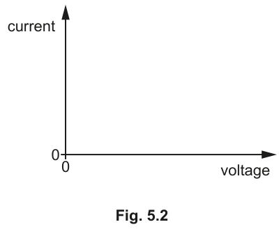
Answer
A curve starting at the origin, rising steeply at first and then bending towards the voltage axis (gradient decreasing).
Walkthrough
The graph plots current (y-axis) against voltage (x-axis). For an ohmic conductor at constant temperature, this would be a straight line through the origin (). However, for a filament lamp, as the voltage increases, the current increases, causing the filament to heat up. The temperature rise causes the resistance of the tungsten filament to increase. Since , a increasing means the current increases less than proportionally with voltage. On an I-V graph, the gradient is . As increases, the gradient decreases. Therefore, the curve starts steep and bends to become flatter, approaching the voltage axis.
Key Takeaways
The current-voltage graph for a filament lamp is non-linear because resistance is not constant; it increases with temperature.
Common Mistakes
- Drawing a straight line (this would be for an ohmic conductor like a fixed resistor at constant temperature).
- Bending the curve the wrong way (towards the current axis), which would imply resistance is decreasing.
Things to Be Careful About
Check which quantity is on the y-axis and which is on the x-axis. Here, current is on the y-axis, so a decreasing gradient means the curve flattens out. If voltage were on the y-axis, the curve would bend upwards.
Answer
As the current (or voltage) increases, the temperature of the filament increases.
As the temperature increases, the resistance of the filament increases.
This causes the current to increase less than proportionally with voltage, giving a curve with a decreasing gradient.
At higher current/voltage, temperature increases; this causes the resistance to increase.
Walkthrough
The shape of the graph is determined by how resistance changes. In a filament lamp, the filament is made of tungsten. As current flows, electrical energy is converted to thermal energy, heating the filament. The resistance of a metal conductor increases as its temperature increases. Therefore, at higher voltages and currents, the filament is hotter and has a higher resistance. This higher resistance limits the current more than it would at lower temperatures, causing the graph to curve.
Key Takeaways
Resistance in metallic conductors is not always constant; it depends on temperature. Filament lamps are non-ohmic devices.
Common Mistakes
- Saying 'resistance increases because voltage increases' without mentioning temperature. The direct cause is temperature.
- Saying 'current decreases' (current still increases, just at a slower rate).
Things to Be Careful About
The mark scheme awards one mark for 'temperature increases' and one mark for 'resistance increases'. Both links in the chain must be stated clearly.
Working
Point P is on the main rail supplying only the two heaters (40 Ω and 60 Ω), not the lamp. The heaters are in parallel across the 240 V supply.
Current in the 40 Ω heater:
Current in the 60 Ω heater:
Total current at point P:
Alternatively, using total resistance of the two heaters in parallel:
Answer
current = 10 A
10 A
Walkthrough
First, locate point P in the circuit diagram. Point P is on the top rail (live wire side) after the lamp branch has connected but before the two heater branches. This means the current at P is the combined current flowing to the 40 Ω and 60 Ω heaters. The lamp current does not pass through point P.
Since the heaters are in parallel, the voltage across each is the full mains supply voltage, 240 V.
Using Ohm's law ():
- Current through 40 Ω heater = A.
- Current through 60 Ω heater = A.
In a parallel circuit, the total current supplied to the branches is the sum of the individual branch currents:
.
Key Takeaways
In a parallel circuit, the voltage across each branch is the same. The current at any point on the main line before a set of parallel branches is the sum of the currents through those branches.
Common Mistakes
- Including the lamp current (1.5 A) in the calculation. Point P is after the lamp branch, so the lamp current does not flow through P.
- Calculating the total resistance of all three components (lamp, 40 Ω, 60 Ω) instead of just the two heaters.
Things to Be Careful About
Read the circuit diagram carefully to determine exactly which components are 'downstream' of point P. Units must be included in the final answer.
The current in the lamp is .
Answer
Total normal operating current = current in lamp + current at P
A suitable fuse rating is any standard value above 11.5 A but not excessively large, such as:
13 A (or 15 A, 17 A, 19 A)
13 A
Walkthrough
The fuse must be rated slightly higher than the normal operating current of the circuit so that it does not blow during normal use, but low enough to blow quickly if a fault causes a dangerous current.
Normal operating current = lamp current + heater current = .
Standard fuse ratings are typically 3 A, 5 A, 13 A, 20 A, 30 A, etc. A 13 A fuse is the smallest standard rating above 11.5 A, making it suitable. Values up to 19 A are also accepted by the mark scheme as long as they are not so large that they fail to protect the circuit.
Key Takeaways
Fuse ratings must be chosen to be above the normal working current but below the current that would damage the wiring or cause a fire.
Common Mistakes
- Suggesting a fuse rating lower than 11.5 A (e.g., 10 A), which would blow during normal operation.
- Suggesting a very large rating like 30 A, which would not protect the circuit.
Things to Be Careful About
The question asks for 'a suitable fuse rating'. Any integer between 12 A and 19 A is acceptable. 13 A is the most common practical choice for a 240 V domestic circuit of this size.
Answer
If the fuse rating is much larger than necessary:
- The fuse will not melt (or blow) quickly enough when a fault occurs.
- The circuit will not be shut down when the current becomes large or dangerous.
- This could cause the wires to overheat, potentially leading to a fire or damage to the appliances.
The fuse would not melt quickly enough during a fault to cut off the current and prevent overheating or fire.
Walkthrough
A fuse is a safety device. Its purpose is to melt and break the circuit when the current exceeds a safe value (a fault current). If a fuse with a very large rating (e.g., 30 A) is used in a circuit that normally draws 11.5 A, a fault might cause a current of 20 A. This is dangerous and could overheat the cables, but the 30 A fuse would not melt, so the circuit would remain live and the danger would persist.
Key Takeaways
Fuses protect circuits by melting when current is too high. A correctly rated fuse ensures protection without nuisance blowing.
Common Mistakes
- Saying 'the fuse would not work' (it does work, just too late).
- Not mentioning that the circuit needs to be shut down or that overheating/danger is the consequence.
Things to Be Careful About
Focus on the consequence of the fuse not blowing: the current remains large/dangerous, and the circuit does not shut down quickly enough.
Explain why it is necessary to connect a fuse in the live wire rather than the neutral wire or earth wire.
Answer
The live wire carries the alternating voltage from the supply. If the fuse is in the live wire and it melts:
- The supply of voltage to the rest of the circuit is cut off.
- No part of the circuit downstream of the fuse will be live, preventing electrocution.
If the fuse were in the neutral wire, the circuit could still be live (at mains voltage) even after the fuse blows, which is dangerous.
When the fuse melts in the live wire, the voltage supply is cut and nothing downstream is live, preventing electrocution.
Walkthrough
In a mains supply, the live wire carries the high alternating voltage (240 V in the UK), while the neutral wire is at approximately 0 V. If a fault occurs and the fuse melts in the live wire, the connection to the high voltage is broken. The rest of the circuit (the lamp, the heaters, the wiring) is no longer connected to the live supply and is safe to touch.
If the fuse were placed in the neutral wire, melting it would break the circuit and stop the current from flowing, so the appliances would stop working. However, the live wire would still be connected to the appliances, meaning they would still be at 240 V. If a person touched the appliance internals, they could receive a fatal electric shock.
Key Takeaways
Safety devices like fuses must be placed in the live wire to ensure the circuit is de-energised when they operate.
Common Mistakes
- Saying 'the earth wire carries the current' (earth is a safety wire, not a current-carrying wire under normal conditions).
- Not explaining that cutting the live wire makes the rest of the circuit safe (not live).
Things to Be Careful About
Be precise with terminology: use 'live', 'voltage', 'electrocution', or 'dangerous' rather than vague terms like 'electricity' or 'power'.
Fig. 6.1 shows the structure of a simple electric motor.
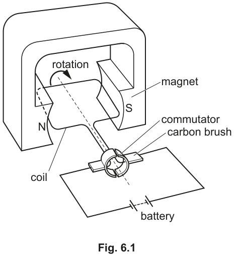
The current in the coil causes the coil to rotate.
A student notices that the coil turns in the direction shown by the curved arrow in Fig. 6.1.
Answer
The motor turns faster (or the coil experiences a stronger force / the turning effect is larger).
The motor turns faster (or the coil experiences a stronger force / larger turning effect).
Walkthrough
The force on a current-carrying conductor in a magnetic field is proportional to the magnetic flux density. Using a stronger magnet increases the magnetic field strength, which increases the force on each side of the coil. This larger force creates a larger turning effect (moment) about the axis, so the coil accelerates more and the motor turns faster.
Key Takeaways
A stronger magnetic field increases the force on a current-carrying conductor, leading to a larger turning effect in a motor.
Common Mistakes
Students often write 'the motor works better' without specifying what happens (e.g., turns faster, stronger force). 'Larger current' is incorrect because the question asks about changing the magnet, not the power supply.
Things to Be Careful About
Accept any valid statement linking the stronger magnet to a larger force, larger moment, or faster rotation. Avoid vague answers like 'more powerful' without context.
On Fig. 6.1 mark and label:
- the direction of the current in the coil
- the direction of the magnetic field.
Answer
- Magnetic field: Draw arrows pointing from the N pole to the S pole (left to right across the gap between the magnets).
- Current direction: Trace from the longer line (positive terminal) of the battery. The current flows up through the right carbon brush, into the right half of the commutator, along the right side of the coil (away from the viewer), across the back, along the left side of the coil (towards the viewer), down through the left half of the commutator, and back to the negative terminal. Mark arrows on the coil sides showing current flowing towards the viewer on the left side and away from the viewer on the right side.
Magnetic field: left to right (N to S). Current: towards viewer on left side of coil, away from viewer on right side.
Walkthrough
Magnetic field direction: Magnetic field lines outside a magnet always point from the North pole to the South pole. In Fig. 6.1, the N pole is on the left and the S pole is on the right, so draw arrows pointing from left to right across the gap between the magnets.
Current direction: Look at the battery symbol. The longer vertical line is the positive terminal, and the shorter, thicker line is the negative terminal. Current flows from positive to negative in the external circuit. Follow the wire from the positive terminal to the right carbon brush. The current goes up into the right half of the split-ring commutator, then into the right side of the coil. Following the coil around, the current goes along the right side (away from you), across the back, along the left side (towards you), down the left side of the commutator, and back to the negative terminal. Mark arrows on the visible front-facing parts of the coil to show this direction.
Key Takeaways
Magnetic field lines go from N to S. Current flows from the positive (longer line) to the negative (shorter line) terminal of a battery in the external circuit.
Common Mistakes
Drawing the magnetic field from S to N. Getting the battery polarity wrong (the longer line is positive). Forgetting to show the current direction on the coil sides themselves, not just the wires.
Things to Be Careful About
The question asks to mark and label on Fig. 6.1. Ensure arrows are clearly drawn on the coil and in the magnetic field gap. Labels like 'N to S' and 'current' are helpful but the arrows themselves carry the marks.
Answer
The current in the coil sides and the magnetic field cause a force on each side of the coil (the motor effect).
Using Fleming's left-hand rule (or the coil-as-a-magnet explanation), the force is upwards on the left side of the coil and downwards on the right side.
These two opposing forces create a turning effect (or couple) that makes the coil rotate.
(Alternative accepted explanation: The current in the coil turns it into a magnet. The top face becomes a North pole and the bottom face a South pole. The North face is repelled by the N pole of the permanent magnet and attracted to the S pole, causing rotation.)
The magnetic field and current cause a force on the sides of the coil. The force is upwards on one side and downwards on the other, creating a turning effect.
Walkthrough
A current-carrying conductor in a magnetic field experiences a force. This is the motor effect. In the motor, the two long sides of the rectangular coil are perpendicular to the magnetic field, so they experience forces.
To find the direction of the force, use Fleming's left-hand rule (or the right-hand grip rule to find the coil's poles). With the current flowing towards the viewer on the left side and the field pointing left to right, the force on the left side is upwards. With the current flowing away from the viewer on the right side, the force on the right side is downwards.
Because these two equal and opposite forces act on different sides of the coil (not along the same line), they form a couple and produce a turning effect (moment) about the central axis. This is why the coil rotates.
Alternatively, you can explain it using magnetic poles: the current in the coil makes it act like a bar magnet. The face towards the top becomes a North pole. This North pole is repelled by the permanent magnet's North pole and attracted to its South pole, causing the coil to turn.
Key Takeaways
Forces on opposite sides of a current-carrying coil in a magnetic field are in opposite directions, creating a turning effect (couple) that causes rotation.
Common Mistakes
Saying 'the coil is attracted to the magnet' without specifying why it rotates. Forgetting to mention that the forces are in opposite directions on opposite sides. Using 'heat' instead of 'thermal energy' (not applicable here, but a common theme). Saying 'the magnetic field pushes the current' instead of 'the magnetic field exerts a force on the current-carrying conductor'.
Things to Be Careful About
The mark scheme awards one mark for stating that a force is caused (or the coil becomes a magnet), and one mark for explaining the direction of the forces (up on one side, down on the other) or the resulting magnetic poles. Both parts are needed for full marks. Ensure you use the word 'force' or 'turning effect' / 'couple'.
Two vertical wires carry equal currents in opposite directions. They pass at right angles through a piece of card as shown in Fig. 6.2.
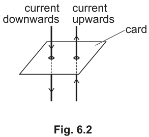
Fig. 6.3 is a view of the card from above.
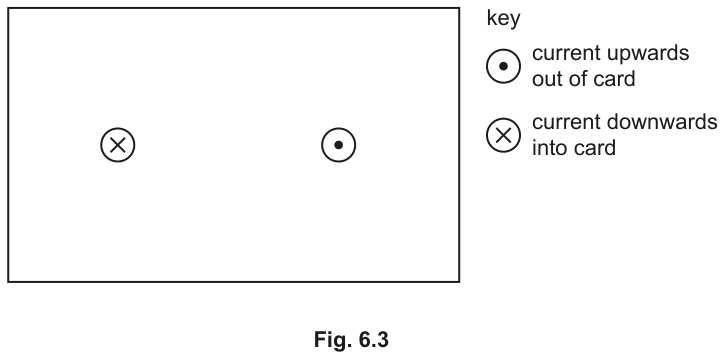
On Fig. 6.3 sketch the pattern of the magnetic field produced.
Indicate the direction of the magnetic field on the pattern that you draw.
Answer
- Draw concentric circles around each wire (the circle with the cross and the circle with the dot).
- Left wire (current into card, cross): Draw clockwise arrows on the circles.
- Right wire (current out of card, dot): Draw anti-clockwise arrows on the circles.
- Overall shape: The circles should be close together near the wires and splay outwards. Between the two wires, the field lines point downwards (from the clockwise field of the left wire and the anti-clockwise field of the right wire both pointing down in the gap), so the field is stronger here. Show this by drawing more closely spaced field lines between the wires.
Concentric circles: clockwise around the left wire (cross), anti-clockwise around the right wire (dot). Field lines point downwards between the wires, showing a stronger field there.
Walkthrough
First, determine the direction of the magnetic field around each individual wire using the right-hand grip rule. Point your right thumb in the direction of the current, and your fingers curl in the direction of the magnetic field lines.
- Left wire: Current is downwards into the card (represented by the cross, like the tail feathers of an arrow). Point your right thumb into the card. Your fingers curl clockwise. Draw concentric circles with clockwise arrows around the left wire.
- Right wire: Current is upwards out of the card (represented by the dot, like the tip of an arrow). Point your right thumb out of the card. Your fingers curl anti-clockwise. Draw concentric circles with anti-clockwise arrows around the right wire.
Next, consider the superposition of these two fields. Between the two wires, the clockwise field from the left wire points downwards, and the anti-clockwise field from the right wire also points downwards. The fields add together, making the magnetic field stronger between the wires. Draw the field lines more closely spaced in this region to indicate the stronger field. Outside the wires, the fields partially cancel and splay outwards.
Key Takeaways
The right-hand grip rule gives the field direction around a straight current-carrying wire. For two parallel wires with opposite currents, the fields between them add together, creating a stronger field.
Common Mistakes
Drawing the field lines as straight lines instead of circles. Getting the direction of the circles wrong (mixing up clockwise and anti-clockwise). Drawing the field lines crossing each other (field lines never cross). Forgetting to show the direction of the field with arrows. Drawing the field lines equally spaced everywhere, missing the stronger field between the wires.
Things to Be Careful About
The question asks to sketch the pattern on Fig. 6.3. Ensure the circles are clearly drawn around the existing cross and dot symbols. The key is provided, so use it correctly: cross is into the page, dot is out of the page. The mark scheme awards one mark for circles close to and around each wire, one for the correct overall shape (stronger between wires), and one for correct direction on at least one line with none wrong. Ensure at least one arrow direction is clearly correct and no arrows are drawn in the wrong direction.
The currents in the two wires cause the wires to repel each other.
Explain how the current in one wire causes a force on the other wire.
Answer
The current in one wire produces a magnetic field at the position of the other wire.
A current-carrying conductor experiences a force when placed in a magnetic field (the motor effect).
Therefore, the magnetic field from the first wire exerts a force on the second wire, and vice versa, causing them to repel.
(Alternative accepted explanation: The magnetic field between the wires is stronger than the field outside. The wires experience a force pushing them away from the region of the strongest magnetic field, causing them to repel.)
The current in one wire produces a magnetic field at the other wire. A current-carrying conductor experiences a force when placed in a magnetic field.
Walkthrough
This question asks for the mechanism behind the force between two current-carrying wires. It is a two-step explanation.
Step 1: The current flowing through the first wire generates a magnetic field around it (Oersted's discovery). This magnetic field extends outwards and is present at the location of the second wire.
Step 2: The second wire also carries a current. When a current-carrying conductor is placed in an external magnetic field, it experiences a force (this is the motor effect, described by ). The magnetic field from the first wire acts on the current in the second wire, producing a force. By Newton's third law, the second wire's field acts on the first wire with an equal and opposite force.
Since the currents are in opposite directions, the forces are repulsive. You can also explain this using field superposition: between the wires, the magnetic fields from both wires point in the same direction and add together, creating a stronger field. Outside the wires, they point in opposite directions and cancel. The wires are pushed away from the region of stronger field towards the region of weaker field, resulting in repulsion.
Key Takeaways
A current-carrying wire produces a magnetic field. Another current-carrying wire in that field experiences a force. This is the fundamental interaction between parallel conductors.
Common Mistakes
Saying 'the wires have magnetic fields so they repel' without explaining the mechanism. Forgetting to mention that the second wire is in a magnetic field. Saying 'the currents repel' (currents are not objects that can repel; the wires do). Using 'heat' or 'thermal energy' incorrectly (not applicable here).
Things to Be Careful About
The mark scheme awards one mark for stating that the current in one wire causes a magnetic field at the other (or that the field between them is stronger), and one mark for stating that a current experiences a force in a magnetic field (or that wires move away from the strongest field). Both parts are needed. Ensure you use the phrase 'magnetic field' and 'force on a current-carrying conductor' or equivalent.
Table 7.1 shows four different nuclei.
Table 7.1
| thorium-236 | protactinium-236 | uranium-235 | uranium-238 |
|---|---|---|---|
Answer
uranium-235 and uranium-238
uranium-235 and uranium-238
Walkthrough
The proton number is the bottom number in the nuclide notation . Reading from Table 7.1:
- thorium-236:
- protactinium-236:
- uranium-235:
- uranium-238:
The two nuclei with the same number of protons (92) are uranium-235 and uranium-238.
Key Takeaways
Nuclide notation is , where is the nucleon number (top) and is the proton number (bottom). Elements with the same proton number are the same element, regardless of the number of neutrons.
Common Mistakes
Confusing the top number (nucleon number) with the bottom number (proton number). Forgetting that the element name is determined solely by the proton number.
Things to Be Careful About
Ensure you are reading the correct subscript for the proton number. In this case, both uranium isotopes have .
Working
The number of neutrons is calculated as:
- thorium-236:
- protactinium-236:
- uranium-235:
- uranium-238:
Answer
thorium-236 and uranium-238
thorium-236 and uranium-238
Walkthrough
Nucleons are the total number of protons and neutrons in the nucleus. To find the number of neutrons, subtract the proton number (, the bottom number) from the nucleon number (, the top number).
Calculating for each:
- : neutrons
- : neutrons
- : neutrons
- : neutrons
Thorium-236 and uranium-238 both have 146 neutrons.
Key Takeaways
Isotopes have the same number of protons but different numbers of neutrons. Nuclei of different elements can have the same number of neutrons (these are called isotones).
Common Mistakes
Assuming that nuclei with the same nucleon number have the same number of neutrons. Forgetting to subtract the proton number from the nucleon number.
Things to Be Careful About
Always perform the subtraction explicitly. A power-of-ten error or misreading the top/bottom numbers will lead to the wrong neutron count.
Answer
thorium-236 and protactinium-236
thorium-236 and protactinium-236
Walkthrough
The nucleon number (also called the mass number) is the top number in the nuclide notation . Looking at Table 7.1:
- thorium-236:
- protactinium-236:
- uranium-235:
- uranium-238:
Thorium-236 and protactinium-236 both have a nucleon number of 236.
Key Takeaways
Nuclei with the same nucleon number but different proton numbers are called isobars. They have the same total number of protons and neutrons combined, but a different ratio of the two.
Common Mistakes
Confusing nucleon number with neutron number or proton number. Remember that the nucleon number is simply the top number in the symbol.
Things to Be Careful About
The nucleon number is an integer and represents the total count of protons and neutrons. Do not confuse it with the atomic mass in atomic mass units, which can be a decimal.
A teacher uses a Geiger-Müller tube and a counter to measure the background radiation in the laboratory.
The counter records 20 counts per minute.
A radioactive source is then placed in front of the tube and the counter records 420 counts per minute.
Answer
Background radiation is the natural radiation present in the environment from natural sources, or radiation present even when no radioactive source is nearby.
Radiation that is natural or present without a specific radioactive source.
Walkthrough
When using a Geiger-Müller tube to measure radiation from a source, the counter will always record some counts even when no source is present. This is because radiation is constantly coming from natural sources in the environment, such as cosmic rays from space, radioactive isotopes in rocks and soil (like radon gas), and even from building materials and food.
To get an accurate measurement of the radiation from the source alone, this background count rate must be subtracted from the total count rate measured when the source is present.
Key Takeaways
Background radiation is unavoidable and must always be accounted for in radioactivity experiments. The corrected count rate from the source is: .
Common Mistakes
Saying 'background radiation is from man-made sources' (this is incorrect; it is primarily natural). Saying 'background radiation is zero' (it is never zero). Forgetting to subtract the background when calculating the source's activity.
Things to Be Careful About
The mark scheme accepts 'natural' or 'present without a source'. Do not just say 'radiation from the ground' as it is too specific; cosmic rays and internal body radiation also contribute.
The measured count rate of 420 counts per minute can be corrected for background radiation.
Calculate the corrected count rate from the source.
count rate = ______ counts per minute
Working
Answer
400
400
Walkthrough
The counter records a total of 420 counts per minute when the source is present. This total includes both the radiation from the source and the background radiation. To find the count rate due to the source alone, subtract the background count rate (20 counts per minute, measured earlier with no source).
Key Takeaways
Always subtract the background count rate to isolate the activity of the radioactive source. This corrected value is what you use for all subsequent half-life calculations.
Common Mistakes
Forgetting to subtract the background radiation and using 420 in the half-life calculation. This will lead to an incorrect final answer.
Things to Be Careful About
Ensure the units are consistent. Both the background and total count rates are in 'counts per minute', so no unit conversion is needed.
The radioactive source has a half-life of 45 minutes.
Determine the reading on the counter 90 minutes later.
reading on counter = ______ counts per minute
Working
Number of half-lives elapsed:
Corrected count rate after 2 half-lives:
Reading on the counter (corrected rate + background):
Answer
120
120
Walkthrough
First, determine how many half-lives have passed in 90 minutes:
Next, halve the corrected count rate (400 counts per minute) for each half-life:
- After 1 half-life (45 minutes): counts per minute
- After 2 half-lives (90 minutes): counts per minute
Finally, the question asks for the 'reading on the counter'. The counter will still detect background radiation, so add the background count rate (20 counts per minute) back to the corrected source count rate:
Key Takeaways
Half-life calculations must be done on the corrected count rate (source only). However, the final answer to 'what will the counter read' must include the background radiation.
Common Mistakes
Forgetting to add the background radiation back at the end. If you stop at 100, you lose the final mark. Halving the uncorrected total (420 -> 210 -> 105) is also incorrect because the background does not decay.
Things to Be Careful About
Read the question carefully: 'reading on the counter' means the total count rate, not the corrected count rate from the source. Always track whether you are working with total or corrected values.
Answer
Radioactive decay is a random process. The actual number of particles emitted in any given time interval will fluctuate around the expected average value.
Radioactive decay is a random process, so the actual count rate will fluctuate around the expected value.
Walkthrough
We cannot predict exactly when a specific nucleus will decay. Radioactive decay is a random, spontaneous process at the level of individual atoms. While the half-life gives us a reliable average for a large number of atoms, the actual count rate measured by a Geiger-Müller tube will show statistical fluctuations (Poisson statistics).
Therefore, the calculated value of 120 counts per minute is an expected average, and the actual reading on the counter at exactly 90 minutes could be slightly higher or lower (e.g., 118 or 123).
Key Takeaways
Half-life is a statistical average that applies to large numbers of nuclei. Individual decay events are random and unpredictable.
Common Mistakes
Saying 'because the half-life changes' (half-life is constant for a given isotope). Saying 'because of human error' (this is not a valid physics reason for the inherent uncertainty in decay counts).
Things to Be Careful About
Use the word 'random' or 'fluctuates'. 'Unpredictable' is also acceptable for individual decays, but 'random' is the precise term used in the syllabus.
Fig. 7.1 shows different uses of three different types of radiation.
Draw a line on Fig. 7.1 from each use of radiation to the type of radiation used. One line has been drawn for you.
Each type of radiation can be used once, more than once or not at all.
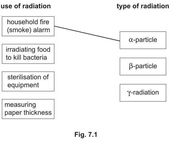
Answer
- irradiating food to kill bacteria → -radiation
- sterilisation of equipment → -radiation
- measuring paper thickness → -particle
See diagram
Walkthrough
We match the uses to the radiation type based on penetration and ionisation:
-
Household fire (smoke) alarm: Already matched to -particle. Alpha particles are strongly ionising but have very low penetration. They are easily blocked by the smoke particles or the casing, making them ideal for detecting smoke in a small chamber.
-
Irradiating food to kill bacteria: Requires radiation that can penetrate deep into the food without making it radioactive. Gamma () radiation is highly penetrating and has low ionising power, making it suitable for sterilising food and medical equipment without damaging the product.
-
Sterilisation of equipment: Same reasoning as food irradiation. Gamma rays are used to sterilise surgical instruments and medical equipment because they can penetrate packaging and kill bacteria throughout.
-
Measuring paper thickness: Requires radiation that is partially absorbed by the paper. Beta () particles have moderate penetration. As the paper gets thicker, more beta particles are absorbed, and the detector count rate drops. Gamma would pass right through without much change, and alpha would be blocked completely by even thin paper.
Key Takeaways
- Alpha (): Strongly ionising, low penetration. Used in smoke alarms.
- Beta (): Moderately ionising, moderate penetration. Used for thickness control of thin materials (paper, foil).
- Gamma (): Weakly ionising, high penetration. Used for sterilisation, food irradiation, and medical imaging.
Common Mistakes
Matching paper thickness to gamma radiation (gamma would pass through without significant absorption). Matching smoke alarms to beta or gamma (they would not be contained within the alarm's detection chamber).
Things to Be Careful About
Note that -radiation is used for both food irradiation and equipment sterilisation. The mark scheme allows each type to be used more than once. Ensure you draw clear lines from the correct boxes.
Table 8.1 shows data about three planets, Mercury, Venus and Earth.
Table 8.1
| time for one orbit of Sun/days | distance from Sun/km | average density | gravitational field strength at surface | |
|---|---|---|---|---|
| Mercury | 88 | 5400 | 3.7 | |
| Venus | 220 | 5200 | 8.9 | |
| Earth | 365 | 5500 | 9.8 |
Fig. 8.1 shows these planets in alignment with the Sun. They rotate around the Sun in the direction shown.
Mark and label on Fig. 8.1 the positions of the three planets 110 days after the position shown in Fig. 8.1.
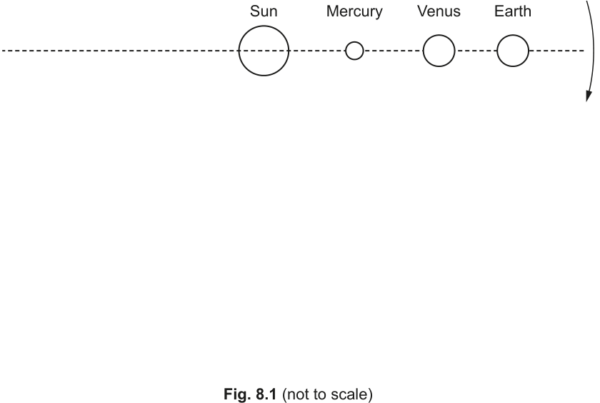
Answer
- Venus: 110 days is exactly half of its 220-day orbit. It moves 180° counter-clockwise, so it is on the dashed line to the left of the Sun.
- Earth: 110 days is approximately 30% of its 365-day orbit (110/365 × 360° ≈ 108°). It is located about 30% of the way around its orbit counter-clockwise, placing it below and slightly to the left of the Sun.
- Mercury: 110 days is 1.25 times its 88-day orbit (110/88 = 1.25). After completing one full orbit, it has moved a further 0.25 of an orbit, which is 90° counter-clockwise. It is located vertically below the Sun.
Venus on left of Sun on dashed line; Earth approx 30% round orbit (108°); Mercury approx 90° (vertically below Sun)
Walkthrough
To find the new positions of the planets, we calculate how far each travels in 110 days as a fraction of its full orbital period, then convert that to an angle.
Mercury:
Orbital period = 88 days.
Fraction of orbit completed in 110 days = .
This means Mercury completes one full orbit (360°) and then a further .
Starting from the right (3 o'clock position) and moving counter-clockwise, 90° places it directly below the Sun (6 o'clock position).
Venus:
Orbital period = 220 days.
Fraction of orbit completed in 110 days = .
This is exactly half an orbit, or .
Moving 180° counter-clockwise from the right places it on the left side of the Sun, on the dashed horizontal line.
Earth:
Orbital period = 365 days.
Fraction of orbit completed in 110 days = .
Angle moved = .
Moving 108° counter-clockwise from the right (past the 90° bottom position) places Earth in the lower-left quadrant, approximately 30% of the way around the orbit.
Key Takeaways
- Orbital period is the time for one complete revolution.
- Angular displacement can be found by multiplying the fraction of the orbital period elapsed by 360°.
- Diagrams must be interpreted with the correct direction of motion (counter-clockwise in this case).
Common Mistakes
- Forgetting to subtract the full orbit for Mercury (110 days is more than one orbit of 88 days).
- Reading the direction of the orbit arrow incorrectly (the arrow on the right pointing down indicates counter-clockwise motion).
- Placing Earth at exactly 90° instead of ~108°.
Things to Be Careful About
- The diagram is not to scale; use the calculated angles to position the planets accurately relative to the Sun.
- Ensure the direction of motion is counter-clockwise as indicated by the arrow.
Each of the three planets has a similar average density.
Suggest why the gravitational field strength at the surface of Mercury is much smaller than at the surface of Venus.
Answer
Gravitational field strength at the surface depends on the mass of the planet. Since Mercury and Venus have similar average densities, Mercury must have a smaller radius and therefore a much smaller mass than Venus. The smaller mass of Mercury results in a weaker gravitational field strength at its surface.
Mercury has a smaller mass
Walkthrough
The gravitational field strength at the surface of a planet is given by , where is the mass and is the radius.
Density , so .
Substituting this into the equation for :
Since the average densities () of Mercury and Venus are similar, is directly proportional to the radius . Mercury has a smaller radius, so it has a smaller mass, which results in a weaker gravitational field strength.
Key Takeaways
- Gravitational field strength depends on both mass and radius.
- For planets with similar densities, the smaller planet will have a weaker surface gravity.
Common Mistakes
- Stating 'smaller size' without linking it to mass.
- Saying 'less gravity' without explaining why.
Things to Be Careful About
- The question asks to 'suggest why', so a clear causal link between mass and gravitational field strength is required.
An object has a weight of on the surface of Mercury.
Calculate its weight on the surface of the Earth. Show your working.
weight = ______
Working
Mass of the object:
Weight on Earth:
Answer
weight = 98 N
98 N
Walkthrough
Weight is given by , where is mass and is gravitational field strength. Mass is constant regardless of location.
Step 1: Find the mass of the object.
Using the weight on Mercury and the gravitational field strength on Mercury:
Step 2: Calculate the weight on Earth.
Using the mass and the gravitational field strength on Earth:
Key Takeaways
- Mass is an intrinsic property and does not change with location.
- Weight depends on the local gravitational field strength.
Common Mistakes
- Forgetting to calculate the mass first and trying to use a direct ratio without showing working.
- Using the wrong value of for Earth (e.g., using 3.7 instead of 9.8).
Things to Be Careful About
- Always show the equation and substitution before the final answer to earn method marks.
- Include units in all calculations.
Answer
A moon is a large, natural object that orbits a planet.
a natural object that orbits a planet
Walkthrough
This is a direct recall question. In the context of the Solar System, a moon (or satellite) is a natural celestial body that orbits a planet.
Key Takeaways
- Moons are natural satellites, distinct from artificial satellites.
- They orbit planets, not stars (stars have planets orbiting them).
Common Mistakes
- Saying 'an object that orbits the Sun' (that is a planet or asteroid).
- Saying 'a small planet' (moons are not classified as planets).
Things to Be Careful About
- Use the word 'natural' to distinguish from artificial satellites like the ISS.
- Specify that it orbits a 'planet'.
The Sun will eventually run out of hydrogen.
Describe what happens to the Sun when the hydrogen runs out.
Answer
- The Sun will expand and become a red giant.
- It will then shed its outer layers to form a planetary nebula.
- Finally, the core will collapse and become a white dwarf.
becomes a red giant, forms a planetary nebula, becomes a white dwarf
Walkthrough
The Sun is a low-mass star (or medium-mass star). When it exhausts the hydrogen fuel in its core, the following sequence occurs:
- Red Giant Phase: Without the outward pressure from hydrogen fusion, the core contracts and heats up. This causes the outer layers to expand dramatically and cool, turning the Sun into a red giant.
- Planetary Nebula: The outer layers of the red giant are eventually ejected into space, forming an expanding shell of gas and dust called a planetary nebula.
- White Dwarf: The remaining hot, dense core is exposed. Without fusion to support it, it slowly cools over billions of years as a white dwarf.
Key Takeaways
- Low-mass stars like the Sun end their lives as white dwarfs.
- The life cycle involves distinct stages: main sequence → red giant → planetary nebula → white dwarf.
Common Mistakes
- Confusing the fate of low-mass stars with high-mass stars (which become neutron stars or black holes).
- Forgetting the planetary nebula stage.
- Saying 'explodes as a supernova' (the Sun is not massive enough).
Things to Be Careful About
- Use the correct terminology: 'red giant', 'planetary nebula', 'white dwarf'.
- The question asks to 'describe what happens', so listing the stages in order is sufficient.