Physics 5054/42 — October/November 2022
Cambridge O-Level · Alternative to Practical · worked solutions for every part, with the mark scheme
Topics Observations and Measurements · Experimental Contexts · Use of Techniques, Apparatus and Materials · Analysis, Conclusions and Evaluation
A student measures the resistance of a lamp for different values of the potential difference across it.
The student connects the circuit shown in Fig. 1.1.
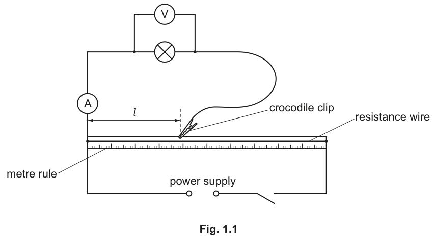
The student:
- closes the switch
- connects the crocodile clip at a length of the resistance wire
- records the potential difference across the lamp
- records the current in the lamp
- opens the switch.
Fig. 1.2 shows the readings on the voltmeter and the ammeter.
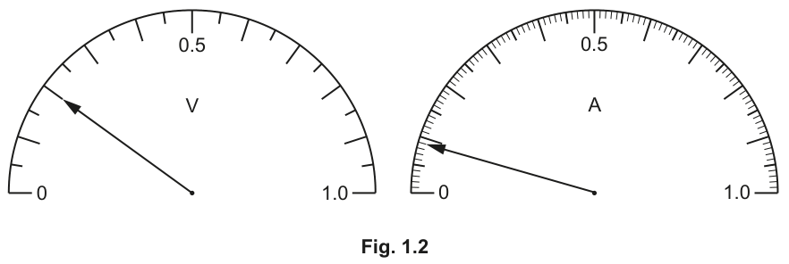
Record in Table 1.1 the values of and .
Table 1.1
| length | potential difference | current | resistance |
|---|---|---|---|
| 10.0 | |||
| 30.0 | 0.7 | 0.13 | 5.4 |
| 50.0 | 1.2 | 0.14 | 8.6 |
| 70.0 | 1.7 | 0.16 | 10.6 |
| 90.0 | 2.2 | 0.19 | 11.6 |
| 100.0 | 2.5 | 11.9 |
The student repeats the procedure with different lengths of the resistance wire.
The student's results are shown in Table 1.1.
Complete the top row of Table 1.1 by calculating the resistance of the lamp when .
Use the equation shown.
The student forgets to write in the current value for .
Calculate the current and write its value in Table 1.1.
The student examines Table 1.1 and states that the resistance of the lamp is directly proportional to the length .
State if you agree with the student's statement.
Justify your answer by using values from Table 1.1.
statement ______
justification ______
On the grid provided in Fig. 1.3, plot a graph of on the -axis against on the -axis.
Start both axes from the origin .
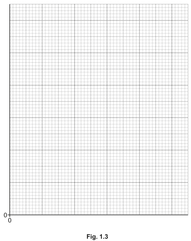
Draw a smooth curve of best fit.
Using your graph, describe how the resistance of the lamp changes as the potential difference across it changes.
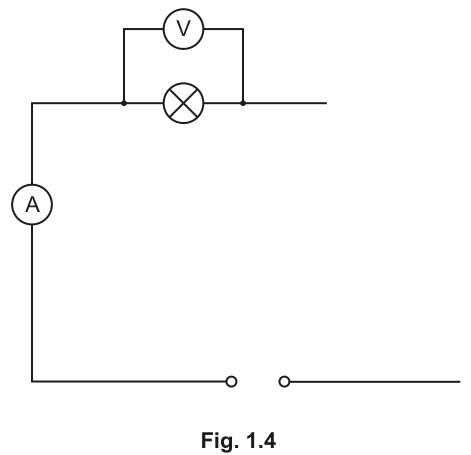
Another student makes changes to the circuit shown in Fig. 1.1.
She uses a variable resistor to vary the current and potential difference, instead of the resistance wire and the crocodile clip.
Complete the circuit diagram in Fig. 1.4 to show how this is done.
The rest of this paper
3 more questions- Q2Experimental Contexts · Observations and Measurements · Analysis, Conclusions and Evaluation9M
- Q3Observations and Measurements · Experimental Contexts · Use of Techniques, Apparatus and Materials5M
- Q4Experimental Contexts · Use of Techniques, Apparatus and Materials · Observations and Measurements3M