Physics 5054/32 — May/June 2021
Cambridge O-Level · Practical Test · worked solutions for every part, with the mark scheme
Topics Experimental Contexts · Observations and Measurements · Analysis, Conclusions and Evaluation · Use of Techniques, Apparatus and Materials
In this experiment you will investigate reflection and refraction of light.
You are provided with:
- a transparent block
- an illuminated slit or ray box
- a ruler
- a protractor.
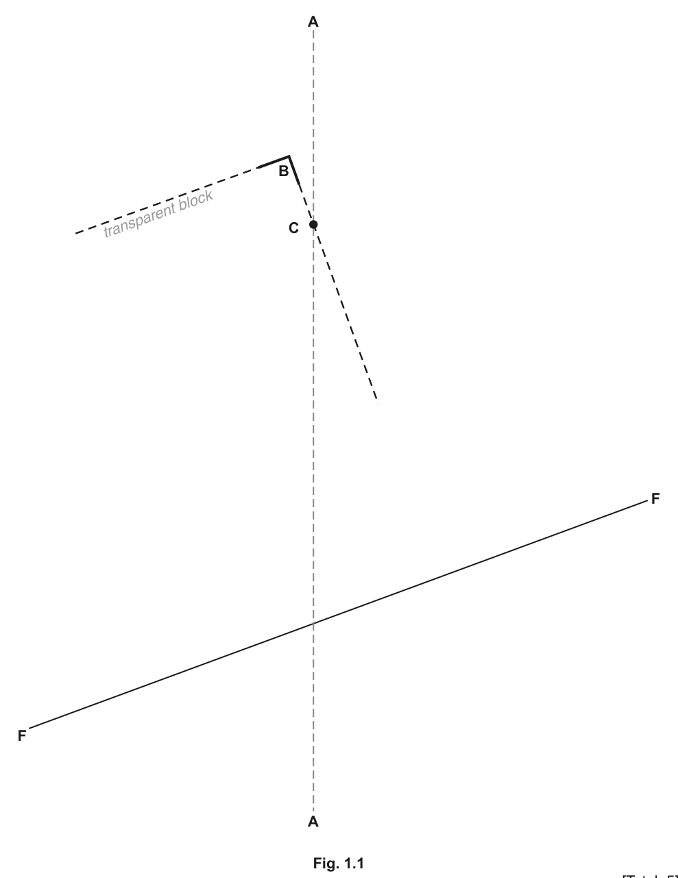
Fig. 1.1 is on page 3 of your question paper. On Fig. 1.1:
- switch on the lamp or ray box and position the slit at the top of the page so that a single ray of light lines up with the line AA
- place the block on Fig. 1.1 and line up the corner of the block with the corner at B so that the ray of light passes through the long edge of the block at the point labelled C
- mark with the letter D the point where the refracted ray emerges from the other side of the block
- mark with the letter E the point where this refracted ray passes through line FF
- draw a line from point D to point E
- mark with the letter G the point where the reflected ray from point C passes through line FF
- draw a line from point C to point G.
Answer
Draw a solid line from C through the block to the point D where the refracted ray emerges from the opposite long edge. Extend this line to intersect line FF at point E. Draw a solid line from C to point G, where the reflected ray intersects line FF. Ensure both C and G lie on line FF, and that the lines are drawn straight from the marked points.
See working
Walkthrough
The experiment investigates how light behaves when it strikes a boundary between two media (air and the transparent block). At point C, the incident ray splits into two: a reflected ray that bounces back into the air, and a refracted ray that passes through the block and emerges from the opposite side. The candidate must trace both paths. The refracted ray is extended past the block to meet line FF at E. The reflected ray is extended to meet line FF at G. Drawing straight lines from C to G and D to E completes the ray diagram.
Key Takeaways
- Light undergoes both reflection and refraction at a transparent boundary.
- The reflected ray stays in the original medium, while the refracted ray enters the second medium.
- Extending the rays to a reference line allows quantitative comparison of their positions.
Common Mistakes
- Forgetting to extend the refracted ray past the block to point E.
- Drawing the reflected ray on the wrong side of the normal (it must be in the same medium as the incident ray, i.e., above the block surface).
- Not drawing straight lines from the marked points.
Things to Be Careful About
- The diagram must be drawn 'by eye' to the precision of the ray box and block. Small deviations are acceptable as long as the geometry is physically correct (angles of reflection and refraction are reasonable).
Measure and record the distance between point E and point G.
= ______
Answer
Using a ruler, measure the straight-line distance between point E and point G along line FF. Record the value to 1 decimal place.
(example value; any correct measurement from the candidate's diagram is accepted)
Candidate-dependent reading; e.g. 4.5 cm
Walkthrough
The distance is the separation between the emergent refracted ray (point E) and the reflected ray (point G) where they cross the reference line FF. The candidate places the ruler along FF and reads the distance between the two marks. Because this is a practical experiment, the exact value depends on the candidate's drawing and the specific block used.
Key Takeaways
- Physical quantities in practical experiments must be recorded to the precision of the measuring instrument.
- A ruler should be read to the nearest millimetre, with a trailing zero if necessary (e.g. 4.5 cm, not 4.50 cm unless the scale supports it).
Common Mistakes
- Reading the wrong end of the ruler or not aligning the zero mark with point E.
- Recording the answer without a unit (the unit 'cm' is printed in the question, but the value must match the scale).
Things to Be Careful About
- Ensure the measurement is taken along the line FF, not a perpendicular distance between the two rays. Read to the precision of the ruler (typically 1 mm or 0.1 cm).
Remove the block.
On Fig. 1.1, draw the normal to the surface of the block at point C and label with an the angle of incidence of the ray of light with the block.
Measure and record the angle of incidence .
= ______
Working
Place the centre of the protractor at point C and its baseline along the surface of the transparent block. Draw a dashed line perpendicular to the block surface at C, extending on both sides of the interface. This is the normal. Measure the angle between the incident ray (from A to C) and the normal on the air side. Label this angle .
Answer
(accepted range )
67
Walkthrough
The angle of incidence is defined as the angle between the incident ray and the normal to the surface at the point of incidence. To find it, the candidate must first draw the normal: a line perpendicular to the block's surface at point C, extending into both the air and the block. The protractor is then placed with its centre at C and its line along the normal (or along the surface, reading the mark). The angle is read between the normal and the incident ray AA. In the mark scheme's model diagram, this angle is .
Key Takeaways
- The normal is always perpendicular to the boundary surface at the point of incidence.
- The angle of incidence is always measured from the normal, not from the surface.
- Angles in optics are typically measured to the nearest degree.
Common Mistakes
- Measuring the angle between the incident ray and the surface instead of the normal (this would give ).
- Drawing the normal at an angle to the surface.
- Forgetting to label the angle .
Things to Be Careful About
- The normal must be drawn on both sides of the interface (air and block) to clearly show the reference line. Allow a tolerance of to account for drawing imprecision. Ensure the protractor is centred exactly on C.
Place the block again on page 3 with its corner lined up at corner B. Carefully rotate the long edge of the block about the point C and observe how this changes the position of the refracted and reflected rays that pass through FF. Switch off the lamp.
Describe the relationship between and .
Answer
As the angle of incidence increases, the distance between E and G decreases.
(Or equivalently: as decreases, increases.)
As i increases, d decreases
Walkthrough
When the block is rotated about point C, the angle of incidence changes. As increases, the reflected ray moves further away from the normal, but the refracted ray also changes direction. In this specific apparatus setup, increasing causes the emergent refracted ray (point E) to move closer to the reflected ray (point G) on line FF, reducing the distance . The candidate must describe this trend based on their observations.
Key Takeaways
- Changing the angle of incidence alters both the reflected and refracted ray paths.
- Experimental observations must be summarised as a clear trend or relationship between the variables.
Common Mistakes
- Stating 'they are equal' or 'there is no relationship' without justification.
- Confusing which variable is independent (, changed by rotating the block) and which is dependent (, measured as a result).
Things to Be Careful About
- The answer must be a directional relationship ('as X increases, Y decreases'). Simply saying 'they are related' is not sufficient. Ensure the direction of the relationship matches the actual physics of the setup (in this case, and are inversely related).
The rest of this paper
3 more questions- Q2Observations and Measurements · Experimental Contexts · Analysis, Conclusions and Evaluation · Use of Techniques, Apparatus and Materials5M
- Q3Use of Techniques, Apparatus and Materials · Observations and Measurements · Experimental Contexts5M
- Q4Experimental Contexts · Observations and Measurements · Use of Techniques, Apparatus and Materials · Analysis, Conclusions and Evaluation15M