Physics 5054/41 — May/June 2012
Cambridge O-Level · Alternative to Practical · worked solutions for every part, with the mark scheme
Topics Experimental Contexts · Analysis, Conclusions and Evaluation · Observations and Measurements · Use of Techniques, Apparatus and Materials · Planning Experiments and Investigations
A teacher and a group of students investigate the behaviour of a copper wire when stretched by heavy loads.
A long thin copper wire is clamped at one end and passes over a pulley. A 1.0 N load is attached to the other end of the wire, as shown in Fig. 1.1.
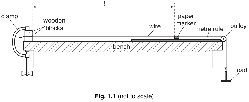
Explain why one end of the wire has to be clamped tightly.
Answer
To secure the end of the wire and prevent it from slipping, ensuring the original length does not change.
To secure the end and prevent slipping, so the original length does not change.
Walkthrough
The experiment measures extension by observing how much the wire stretches under load. If the clamp is loose, the wire can slip through it as the load is applied. This would mean the measured extension includes some slippage, not just actual stretching of the copper. Clamping tightly ensures the fixed end remains truly fixed, so the original length is constant throughout the experiment.
Key Takeaways
In any stretching experiment, the fixed end must be secure so that all measured movement is due to elastic extension of the material, not slippage at the clamp.
Common Mistakes
Saying "to hold the wire" is too vague. The mark requires the idea of preventing slipping or keeping the original length constant.
Things to Be Careful About
Ensure you explain the consequence of not clamping tightly (slipping / changing original length), not just state what the clamp does.
Explain why the students watching the experiment must wear safety glasses.
Answer
If the wire breaks under the heavy load, pieces of wire can fly out and damage eyes. Safety glasses protect against this hazard.
The wire may break and fly out, which is a hazard to the eyes.
Walkthrough
Copper wire under heavy loads can snap suddenly. When it does, the stored elastic potential energy is released, and the broken ends can whip around at high speed. Eye protection is a standard safety requirement for any experiment involving tensioned wires, springs, or rubber bands.
Key Takeaways
Always wear eye protection when working with materials under high tension, as sudden failure can launch fragments.
Common Mistakes
Saying "because it is dangerous" is not specific enough. The mark requires linking the hazard to the eyes (damages eye) and the cause (breaking wire).
Things to Be Careful About
Do not say "heat" or "electricity" — this is a mechanical stretching experiment. The hazard is purely mechanical failure of the wire.
A paper marker is attached to the wire. The length of the wire from the wooden blocks to the marker is measured.
The marker and metre rule are used to measure the extension of the wire as the load is increased.
State what is meant by extension.
Answer
Extension is the increase in length from the original (unstretched) length.
The increase in length from the original length.
Walkthrough
Extension is a standard term in mechanics and material science. It is defined strictly as the change in length from the original, unloaded length: . It is not the total length .
Key Takeaways
Extension is always measured from the original unstretched length, not from zero or from the clamp.
Common Mistakes
Saying "the new length" or "the total length" is wrong. The mark requires "increase in length".
Things to Be Careful About
Be precise with wording. "Increase in length" is the key phrase.
Explain why the marker is attached a long distance from the clamped end of the wire.
Answer
A longer original length produces a larger extension for the same load, making the movement of the marker easier to measure.
A longer wire produces a larger extension for the same load, making it easier to measure.
Walkthrough
The extension of a wire is proportional to its original length (from Hooke's law and the definition of strain). By using a long wire, the extension for a given load is larger, which means the marker moves further. This reduces the percentage error when reading the scale.
Key Takeaways
In wire-stretching experiments, use a long wire to amplify the extension and improve measurement precision.
Common Mistakes
Saying "to make the experiment take longer" is irrelevant. The mark requires the link between longer length and larger extension.
Things to Be Careful About
Do not say "to make it stretch more" without explaining why that is useful (easier to measure).
Explain why some distance is left between the marker and the pulley.
Answer
To allow room for the marker to move as the wire extends, so it does not hit the pulley.
To allow space for the marker to move as the wire extends.
Walkthrough
As the load is increased, the wire stretches and the marker moves to the right. If the marker is placed too close to the pulley, it will collide with the pulley or run out of rule before the full range of loads can be tested. Leaving a gap ensures the marker stays on the rule for all readings.
Key Takeaways
Always ensure apparatus has enough travel range for the expected maximum movement.
Common Mistakes
Saying "to let the wire hang" is wrong. The mark requires the idea of allowing movement of the marker.
Things to Be Careful About
Focus on the marker's movement, not the wire's movement.
Fig. 1.2 shows a magnified view of the wire, marker and rule.
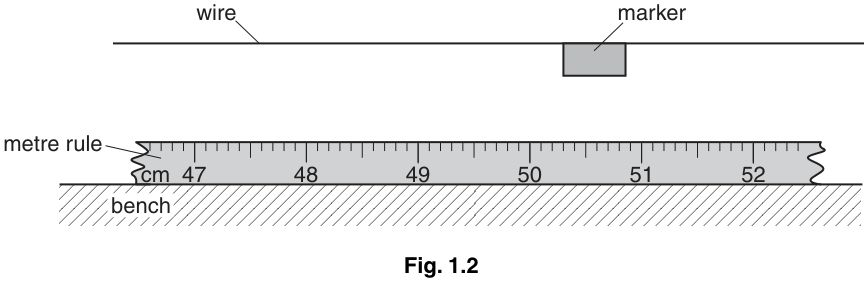
The left-hand side of the marker is used as the reference point.
Use Fig. 1.2 to find the position of the marker.
position = _____
Answer
position = 50.3 cm
(Note: 50.4 cm is also acceptable depending on exact alignment, but 50.3 cm is the scheme value.)
50.3 cm
Walkthrough
The metre rule has major divisions at every cm and minor divisions at every 1 mm. The left-hand edge of the marker is between 50.3 and 50.4 cm. Reading to one decimal place in cm (i.e., to the nearest mm) gives 50.3 cm. Always include the unit.
Key Takeaways
When reading a scale, estimate to one more decimal place than the smallest division. For a 1 mm scale, read to 0.1 mm or 0.01 cm. Here, 50.3 cm is to the nearest mm.
Common Mistakes
Writing "50.3" without the unit "cm" will lose the mark. Writing "503 mm" is also correct but must match the scale shown.
Things to Be Careful About
The question specifies the left-hand side is the reference point. Ensure you read the left edge, not the right edge (which would be ~50.7 cm).
Suggest why a small 1.0 N load is added before the initial reading of the position of the marker is found.
Answer
To tension the wire and remove any kinks, ensuring the wire is straight before taking the initial reading.
To tension the wire and remove kinks so it is straight.
Walkthrough
A loose wire may have small bends or kinks in it. When the first load is applied, these kinks will straighten out, causing an apparent extension that is not real elastic stretching. Adding a small initial load (like 1.0 N) removes the slack and straightens the wire, so all subsequent readings measure true elastic extension.
Key Takeaways
Always apply a small initial load to remove slack in wire or spring experiments before taking the zero reading.
Common Mistakes
Saying "to stretch the wire" is too vague. The mark requires "remove kinks" or "straighten" or "tension".
Things to Be Careful About
The 1.0 N load is already mentioned in the stem as being attached. This part asks why it is added before the initial reading.
Explain why it is difficult for a student to read the position of the marker accurately.
Answer
There is a distance between the marker edge and the ruler scale. If the student views the marker from an angle, parallax error occurs. Also, the edge of the marker may not be perfectly vertical, making it hard to align with the scale.
There is a gap between the marker and the ruler, causing parallax error if viewed from an angle, and the marker edge may not be vertical.
Walkthrough
The marker is attached to the wire, which is above the bench. The rule lies on the bench. There is a vertical gap between the marker and the scale. To read the position accurately, the eye must be directly above the marker edge. If the eye is off to the side, the marker appears to be at a different position on the scale (parallax error). Additionally, the paper marker's edge may be slightly slanted, making it hard to know exactly where the edge is.
Key Takeaways
Parallax error occurs when the object being read is not in the same plane as the scale. Always view scales at right angles.
Common Mistakes
Saying "the marker is too small" is not the main reason. The mark requires "distance between marker and ruler" or "not vertical" or "difficult to view from above".
Things to Be Careful About
Do not just say "parallax" — explain why parallax is a problem here (the gap between marker and scale).
Describe one change to the apparatus to make it easier to read the position of the marker accurately.
Answer
Raise the ruler so it touches the marker, or use a set square against the marker edge to read the scale. Alternatively, use a larger, more clearly defined marker.
Raise the ruler to touch the marker, or use a set square against the marker edge to read the scale.
Walkthrough
To eliminate parallax error, the scale must be as close as possible to the object being read. Raising the metre rule so it is flush with the marker removes the vertical gap. Alternatively, a set square can be placed against the marker edge with one edge on the scale, ensuring the reading is taken at right angles. A larger marker with sharper edges also makes alignment easier.
Key Takeaways
To reduce parallax error, bring the scale and the object being read into the same plane, or use a sighting device like a set square.
Common Mistakes
Saying "use a better ruler" is too vague. The mark requires a specific change like "raise ruler" or "use set square" or "larger marker".
Things to Be Careful About
The suggestion must directly address the problem identified in part (iii) (parallax / gap / non-vertical edge).
One of the students takes a series of readings of the extension of the wire as the load is increased, as shown in Fig. 1.3.
Fig. 1.3
| 1.0 | 0 |
| 6.0 | 7 |
| 11.0 | 13 |
| 16.0 | 21 |
| 21.0 | 26 |
| 26.0 | 33 |
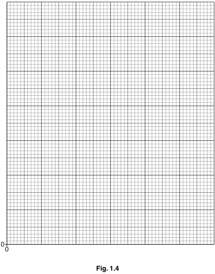
On Fig. 1.4, plot the graph of on the -axis against on the -axis. Start your axes from the origin. Draw the line of best fit.
Working
Axes:
- x-axis: , range 0 to 26, scale e.g. 2 cm = 5 N
- y-axis: , range 0 to 33, scale e.g. 2 cm = 5 mm
Points plotted:
(1.0, 0), (6.0, 7), (11.0, 13), (16.0, 21), (21.0, 26), (26.0, 33)
Line of best fit:
A straight line drawn through or near most points, balancing points above and below the line. The line should not necessarily pass through (0,0) as there is an initial 1.0 N load.
Answer
Graph plotted with correct axes, scales, points, and line of best fit.
Graph with axes labelled F/N and e/mm, points plotted accurately, and a straight line of best fit drawn.
Walkthrough
- Axes labels: Both axes must have the quantity and unit: on the x-axis and on the y-axis. The order matters: "e against F" means e is on the y-axis.
- Scales: Choose scales that use more than half the grid. For x-axis (0 to 26), a scale of 2 cm = 5 N works well (26 N fits in ~26 cm). For y-axis (0 to 33), a scale of 2 cm = 5 mm works well (33 mm fits in ~33 cm).
- Plotting points: Plot each pair from the table. (1.0, 0), (6.0, 7), (11.0, 13), (16.0, 21), (21.0, 26), (26.0, 33). Points must be plotted to within half a small square.
- Line of best fit: Draw a straight line that balances the points on either side. Do not force it through (0,0) because the first reading is at 1.0 N, not 0 N. The line should pass near (1.0, 0) and extend through the other points.
Key Takeaways
When plotting graphs: label axes with quantity and unit, use sensible scales, plot points accurately, and draw a balanced line of best fit (not a line joining all points).
Common Mistakes
- Forgetting units on axis labels.
- Forcing the line through the origin (0,0) when the data does not support it.
- Joining the points with a ruler instead of drawing a line of best fit.
- Using awkward scales (e.g., 1 cm = 3 N).
Things to Be Careful About
The line of best fit does not have to pass through every point or the origin. It must balance points above and below. The first data point is (1.0, 0), not (0,0), so the line will have a positive x-intercept if extended.
Describe the relationship between and that is shown by your graph.
Answer
The graph is a straight line, so extension is directly proportional to the load (if the line passes through the origin) or extension is linearly related to the load (since it does not pass through the origin).
Extension is linearly related to the load (or directly proportional if the line passes through the origin).
Walkthrough
The graph of extension against load is a straight line. This indicates a linear relationship. If the line passes through the origin (0,0), the relationship is directly proportional (Hooke's law). Since the line does not pass through the origin (due to the initial 1.0 N load), we say extension is linearly related to the load, or that the extension is proportional to the load applied beyond the initial 1.0 N.
Key Takeaways
A straight line graph indicates a linear relationship. Direct proportionality requires the line to pass through the origin.
Common Mistakes
Saying "it is proportional" without qualification is risky if the line doesn't go through the origin. Say "linear" or "directly proportional if through origin".
Things to Be Careful About
The mark scheme accepts "directly proportional only if line within 1 sq of (0,0)" or "linear if not through (0,0)". Be precise.
The teacher continues to increase the load. Describe what happens as the load becomes very large.
Answer
The wire will no longer obey Hooke's law (the graph will curve), it will undergo plastic deformation (permanent extension), and eventually it will break.
The wire will break, or no longer be linear, or undergo permanent deformation.
Walkthrough
As the load increases beyond the elastic limit, the wire will no longer return to its original length when the load is removed (plastic deformation). The graph of extension against load will curve upwards, meaning a small increase in load causes a large increase in extension. Eventually, the stress exceeds the ultimate tensile strength of the copper, and the wire will snap (break).
Key Takeaways
Materials have an elastic limit. Beyond this, they deform permanently and eventually fracture.
Common Mistakes
Saying "it will stretch more" is too vague. The mark requires "breaks", "no longer linear", or "plastic extension".
Things to Be Careful About
The question asks what happens as the load becomes very large. Focus on the final outcome: breaking or permanent deformation.
The rest of this paper
3 more questions- Q2Observations and Measurements · Experimental Contexts · Analysis, Conclusions and Evaluation4M
- Q3Experimental Contexts · Planning Experiments and Investigations · Analysis, Conclusions and Evaluation5M
- Q4Experimental Contexts · Use of Techniques, Apparatus and Materials · Observations and Measurements · Planning Experiments and Investigations · Analysis, Conclusions and Evaluation6M